Repair:
If choke will not heat properly, check for
broken heater wire, high-resistance connections, or
broken lead wires to the bi-metal and heater assem-
bly. With the element at room temperature, check the
heater resistance with an ohmmeter. The resistance
should be about 30.6 to 37.4 ohms for a 12 volt sys-
tem. If the heater is defective, replace
it
with a new
one. When the start button is engaged, the solenoid
should cause the spring-loaded armature to contact
the solenoid core.
If this does not occur, check for broken lead wiresora
defective solenoid coil. There must be slack in the
lead wires between the choke body and the bi-metal
'
and heater assembly. The solenoid coil resistance
should be 2.09 to 2.31 ohms in a 12 volt system.
When replacing the cover on the thermostat and
heater assembly, be certain that the choke heater
lead wires have been correctly installed in the choke
housing. Improper replacement of the lead wires can
cause the choke assembly to malfunction.
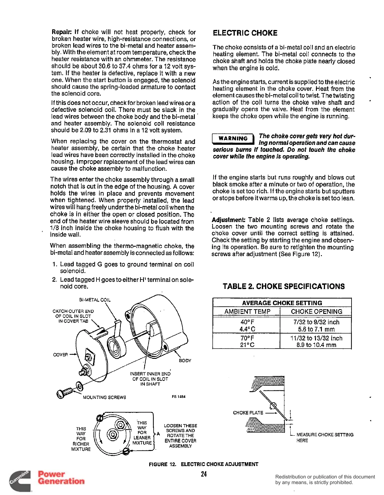
The wires enter the choke assembly through a small
notch that is cut in the edge
of
the housing.
A
cover
holds the wires in place and prevents movement
when tightened. When properly installed, the lead
wires will hang freely underthe bi-metal coil when the
choke is in either the open or closed position. The
end of the heater wire sleeve should be located from
1/8
inch inside the choke housing to flush with
the
When assembling the thermomagnetic choke, the
bi-metal and heater assembly is connected as follows:
1. Lead tagged
G
goes to ground terminal on coil
2. Lead tagged
H
goes to either
H1
terminal on sole-
'
inside wall.
solenoid
.
noid core.
CATCH
OUTER
END
OF
COIL
IN
SLOT
IN
COVER
TAB
COVER
INSERT
INNER
END
OF
COIL
IN SLOT
IN
SHAFT
MOUNTING
SCREWS
FS
1484
THIS
WAY
FOR
RICHER
MIXTURE
'
FOR
A
LEANER
MIXTURE
i
LOOSEN
THESE
SCREWS
AND
ROTATE
THE
ENTIRE
COVER
ASSEMBLY
ELECTRIC CHOKE
The choke consists
of
a bi-metal coil and an electric
heating element. The bi-metal coil connects to the
choke shaft and holds the choke plate nearly closed
when the engine is cold.
As theenginestarts, current is supplied to the electric
heating element in the choke cover. Heat from the
element causes the bi-metal coil to twist. The twisting
action of the coil turns the choke valve shaft and
gradually opens the valve. Heat from the element
keeps the choke open while the engine is running.
'
WARNlNG
The choke cover gets very hot
dur-
-
ing normal operation and can cause
serious burns
if
touched.
Do
not touch the choke
cover while the engine
is
operating.
If
the engine starts but runs roughly and blows out
black smoke after a minute or two of operation, the
choke is set too rich. If the engine starts but sputters
or stops before it warms up, the choke is set too lean.
Adjustment:
Table 2 lists average choke settings.
Loosen the two mounting screws and rotate the
choke cover until the correct setting is attained.
Check the setting by starting the engine and observ-
ing its operation. Be sure to retighten the mounting
screws after adjustment
(See
Figure 12).
TABLE
2.
CHOKE SPECIFICATIONS
L
AVERAGE
CHOKE
SETTING
I
AMBIENT TEMP
I
CHOKE OPENING
I
40"
F
I
7/32 to 9/32 inch
4.4O
c
5.6 to
7.1
rnm
I
70'
F
I
11/32 to 13/32 inch
I
21°C
8.9
to 10.4 mm
CHOKE
PLATE
L
MEASURE
HERE
CHOKE
SETTING
FIGURE
12.
ELECTRIC CHOKE ADJUSTMENT
24
Redistribution or publication of this document
by any means, is strictly prohibited.
Redistribution or publication of this document
by any means, is strictly prohibited.
 Loading...


