If this does not occur, checkfor broken lead wires ora
defective solenoid coil. There must be slack in the
lead wires between the choke body and the bimetal
and heater assembly.
The
solenoid
coil
resistance
should be
2.09
to
2.31
ohms in a
12
volt system.
When replacing
the
cover
on
the
thermostat and
heater assembly, be certain that the choke heater
lead wires have been correctly installed in the choke
housing. Improper replacement
of
the lead wires can
cause the choke assembly to malfunction.
The wires enter the choke assembly through a small
notch that is cut in the edge of the housing.
A
cover
holds the wires in place and prevents movement
when tightened. When properly installed, the lead
wires will hang freely under the bimetal coil when the
choke is in either the open or closed position. The
end of the heater wire sleeve should be located from
1/8
inch inside the choke housing to flush with the
inside wall.
When assembling the thermo-magnetic choke, the
bimetal and heater assembly is connected asfollows:
1.
Lead tagged
G
goes to ground terminal on coil
2.
Lead tagged
H
goes to either
H1
terminal on sole-
solenoid.
noid core.
FUEL
PUMP
A
diaphragm type fuel pump is used. If fuel does not
reach the carburetor, check thefuel pump.
Todo
this,
disconnect the fu.el line at the carburetor and, while
cranking the engine slowly by hand, observewhether
fuel cornesthrough theline. Besurethereisfuel in the
tank. If the line is open and no fuel comes throug h, the
pump is defective. Failure of the pump is usually due
to a leaking diaphragm valve or valve gasket, a weak
or broken spring, or wear in the drive linkage. Oil
diluted with gasoline may indicate a faulty
diaphragm. If the operator chooses to repair the
pump rather than install a new one, the use of a
complete repair kit
is
recommended.
WARNING
Fuel leakage is a fire and explosion
=
hazard fbaf mighf cause severe per-
sonal injury
or
death.
Use
care when reassembling
fuel pump. All parts must align perfectly or pump will
leak fuel.
Fuel
Pump
Reconditioning
1.
2.
3.
Remove fuel lines and mounting screws holding
pump to engine, Figure 6c.
Makea mark with afileacrossapointwhere upper
and lower body join to assure proper reassembly.
Remove four assembly screws and remove upper
pump body.
Turn upper pump body over and remove valve
retainer screws and washers. Remove valve
retainer, valves, valve springs and valve gasket,
noting their position. Discard valve springs,
valves and valve retainer gasket.
i?
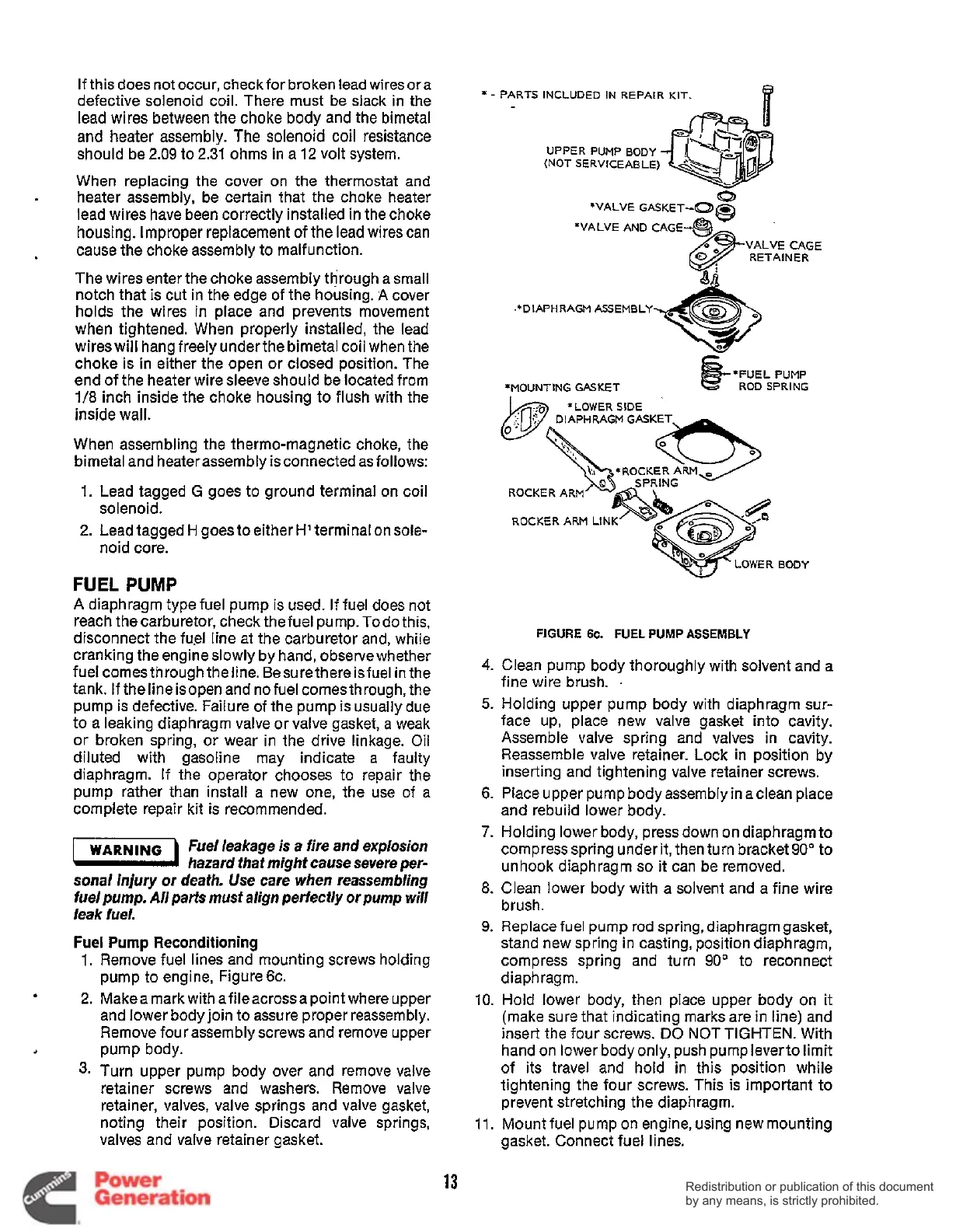
*
-
PARTS
INCLUDED
IN
REPAIR
KIT.
UPPERPUMPBODY
(NOT
SERVICEABLE)
*VALVE
GASKET-Q~
Q
*VALVE
AND
VALVE
CAGE
RETAINER
.*DIAPHRAGM
ASSEMBLY
*FUEL
PUMP
*MOUNTING
GASKET
ROD
SPRING
'LOWER
SIDE
DIAPHRAGM
GASKET
ROCKER
ROCKER
ARM
LINK'^^
BODY
4.
5.
6.
7.
a.
9.
10.
11.
FIGURE
6c.
FUEL
PUMP
ASSEMBLY
Clean pump body thoroughly with solvent and a
fine wire brush.
.
Holding upper pump body with diaphragm sur-
face up, place new valve gasket into cavity.
Assemble valve spring and valves in cavity.
Reassemble valve retainer. Lock in position by
inserting and tightening valve retainer screws.
Place upper pump body assembly in a clean place
and rebuild lower body.
Holding lower body, press down on diaphragmto
compress spring under it, then turn bracket
90"
to
unhook diaphragm
so
it
can be removed.
Clean lower body with a solvent and a fine wire
brush.
Replace fuel pump rod spring, diaphragm gasket,
stand new spring in casting, position diaphragm,
compress spring and turn
90"
to reconnect
d iap
h
rag m.
Hold
lower body, then place upper body on
it
(make sure that indicating marks are in line) and
insert the four screws.
DO
NOT
TIGHTEN.
With
hand
on
lower body only, push pump leverto limit
of its travel and hold in this position while
tightening the four screws. This is important to
prevent stretching the diaphragm.
Mount fuel pump on engine, using new mounting
gasket. Connect fuel lines.
13
Redistribution or publication of this document
by any means, is strictly prohibited.
Redistribution or publication of this document
by any means, is strictly prohibited.
 Loading...


