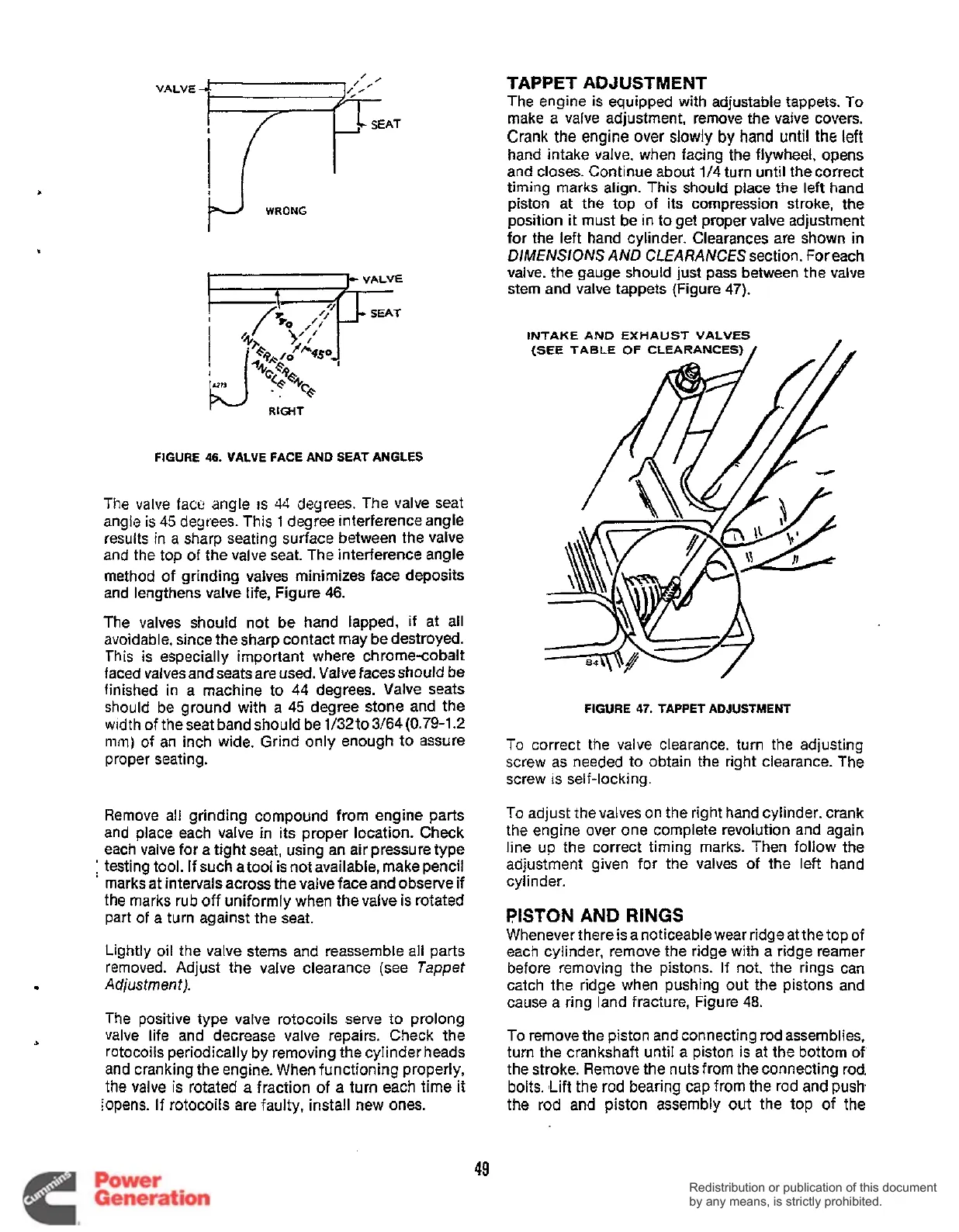
FIGURE
46.
VALVE FACE AND
SEAT
ANGLES
The valve face angle
IS
44
degrees. The valve seat
angle
is
45
degrees. This
1
degree interference angle
results in a sharp seating surface between the valve
and the top
of
the valve seat. The interference angle
method of grinding valves minimizes face deposits
and lengthens valve life, Figure
46.
The valves should not be hand lapped,
if
at all
avoidable, since the sharp contact may be destroyed.
This is especially important where chromecobalt
faced valves and seats are used. Vaive faces should be
finished in a machine to
44
degrees. Valve seats
should be ground with
a
45
degree stone and the
width of theseat bandshould be 1/32to3/64(0.79-1.2
mm)
of an inch wide. Grind only enough to assure
proper seating.
Remove all grinding compound from engine parts
and place each valve in its proper location. Check
each valve for a tight seat, using an air pressure type
:
testing tool. If such a tool
is
not available, make pencil
'
marks at intervals across the valve face and observe if
the marks rub off uniformly when the valve
is
rotated
part
of
a turn against the seat.
Lightly oil the valve stems and reassemble all parts
removed. Adjust the valve clearance (see
Tappet
Adjustment
j.
The positive type valve rotocoils serve to prolong
valve
life
and decrease valve repairs. Check the
rotocoils periodically by removing the cylinder heads
and cranking the engine. When functioning properly,
the
valve
is rotated
a
fraction of
a
turn each time it
iopens. If rotocoils are faulty, install new ones.
TAPPET ADJUSTMENT
The engine
is
equipped with adjustable tappets. To
make a valve adjustment, remove the valve covers.
Crank the engine
over
slowly
by
hand
until
the
left
hand intake valve. when facing the flywheel, opens
and closes. Continue about
1/4
turn until the correct
timing marks align. This should place
the
left hand
piston at the top of its compression stroke, the
position
it
must be in to get proper valve adjustment
for the left hand cylinder. Clearances are shown
in
DIMENSIONS
AND CLEARANCES
section. For each
valve. the gauge should just pass between the valve
stem and valve tappets (Figure
47).
INTAKE
AND
EXHAUST
VALVES
(SEE
TABLE
OF
CLEARANCE
FIGURE
47.
TAPPET
ADJUSTMENT
To
correct the valve clearance, turn the adjusting
screw as needed to obtain the right clearance. The
screw
is
self-locking.
To adjust the valves on the right hand cylinder. crank
the engine over one complete revolution and again
line up the correct timing marks. Then follow the
adjustment given for the valves of the left hand
cylinder.
PISTON AND
RINGS
Whenever there is a noticeable wear ridge at the top
of
each cylinder, remove the ridge with a ridge reamer
before removing the pistons.
If
not. the rings can
catch the ridge when pushing out the pistons and
cause a ring land fracture, Figure
48.
To remove the piston and connecting rod assemblies,
turn the crankshaft until a piston
is
at the bottom of
the stroke. Remove the nuts from the connecting rod,
bolts. ILift the rod bearing cap from the rod and push
the rod and piston assembly out the top of the
49
Redistribution or publication of this document
by any means, is strictly prohibited.
Redistribution or publication of this document
by any means, is strictly prohibited.
 Loading...


