ADJUSTABLE
GOVERNOR
Where engine speed is governor controlled, the
governor is set at the factory to allow a nominal
engine speed of
2400
rprn
at no-load operation
(unless another speed
is
specified when the engine is
ordered). Proper governor adjustment
is
one of the
most important factors in maintaining the power and
speed desired from the engine, Figure 6d.
Linkage
Check the governor arm, linkage, throttle shaft and
lever for a binding condition or excessive slack and
wear at connecting points.
A
binding condition at any
point will cause thegovernortoact slowly and regula-
tion will be poor. Excessive looseness will cause a
hunting condition and regulation will beerratic. Work
the arm back and forth several times by hand while
the engine idles. Replace parts as needed.
.
The engine starts at wide open throttle. The length of
the linkage connecting the goverorarm tothethrottle
arm is adjusted by rotating the ball joint. Adjust length
so
with the engine stopped and tension on the
governor spring, the carburetor throttle lever is wide
open. This setting allows immediate control by the
governor after starting and synchronizes travel of the
governor arm and the throttle shaft.
'
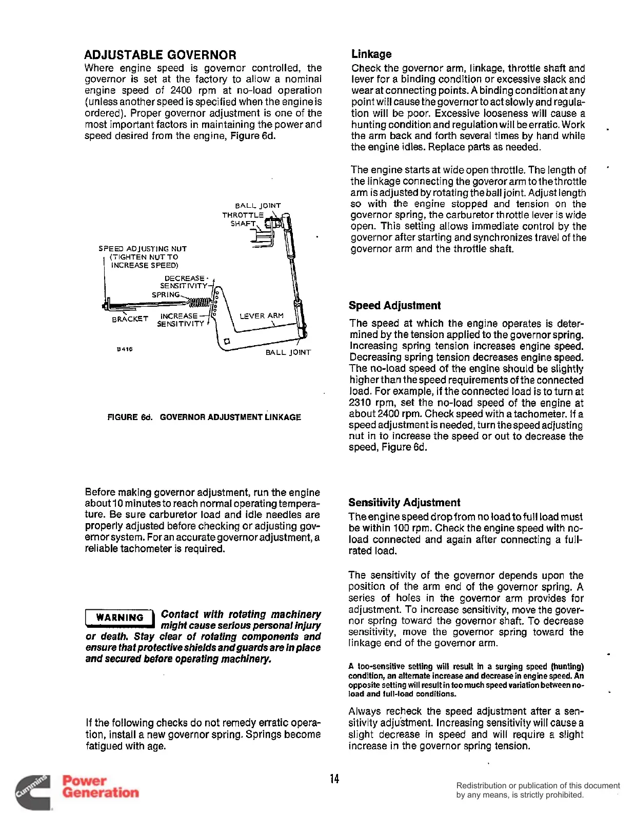
BALL JOINT
SPEED ADJUSTING NUT
(TIGHTEN NUT TO
INCREASE SPEED)
SE NSlT IVlTY
Speed
Adjustment
The speed at which the engine operates
is
deter-
mined by
the
tension applied to the governor spring.
Increasing spring tension increases engine speed.
Decreasing spring tension decreases engine speed.
The no-load speed of the engine should be slightly
higher than the speed requirements
of
the connected
load. For example, if the connected load is to turn at
2310
rpm, set the no-load speed of the engine at
about
2400
rpm. Check speed with a tachometer. If a
speed adjustment is needed, turn the speed adjusting
nut in to increase the speed or out to decrease the
speed, Figure 6d.
8416
FIGURE 6d. GOVERNOR ADJUSTMENT LINKAGE
Before making governor adjustment, run the engine
about
10
minutes to reach normal operating tempera-
ture. Be sure carburetor load and idle needles are
properly adjusted before checking or adjusting gov-
ernor system. For an accurategovernor adjustment,
a
reliable tachometer is required.
Sensitivity Adjustment
Theenginespeeddropfrom no loadtofull load must
be within
100
rpm. Check the engine speed with no-
load connected and again after connecting a full-
rated load.
WARNING
Confacf wifh rofafing machinery
n
mighf cause serious personal injury
or
deafh. Say clear
of
rofating componenfs and
ensure that profecfive shields and guards are in place
and secured before operating machinery.
If the following checks
do
not remedy erratic opera-
tion, install a
new
governor spring. Springs become
fatigued with age.
The sensitivity of the governor depends upon the
position of the arm end of the governor spring.
A
series of holes in the governor arm provides for
adjustment. To increase sensitivity, move the gover-
nor spring toward the governor shaft.
To
decrease
sensitivity, move the governor spring toward the
linkage end of the governor arm.
A
too-sensitive setting will result in a surging speed (hunting)
condition, an alternate increase and decrease in engine speed. An
opposite setting
will
result in too
much
speed variation between no-
load and full-load conditions.
Always recheck the speed adjustment after a sen-
sitivity adjustment. Increasing sensitivity will cause a
slight decrease in speed and will require
a
slight
increase in the governor spring tension.
14
Redistribution or publication of this document
by any means, is strictly prohibited.
Redistribution or publication of this document
by any means, is strictly prohibited.
 Loading...


