Belt
Drive:
V-belts are preferable to flat.belts.
CorfsOTf
a reliable belting supplier for recommendations
regarding size
of
pulleys, number
of
belts, etc.,
required.
A
typical belt drive installation is
shown
in.
Figure 1.
.
Comply with the following installation requirements:
1.
Shafts of engine
and
load must be parallel with
2. Pulleys of engine and load must be in alignment.
3. Mount engine pulleys as close to engine as
possible.
4.
If installation permits, belts should run horizon-,
tally.
5.
Some method of disconnecting the load for
starting
is
recommended. If a clutch is not used, a
belt-tightener idler arrangement can be used.
Flexible Coupling:
If a flexible coupling engine-to-
load drive is used, the load shaft must be
in
line and
‘centered with the eng-ine shaft, Figure 2..
.
each other.
ENGINE POWER
.
FLEXIBLE
FIGURE
2
FLEXIBLE COUPLING
Reduction Gear Drive:
Reduction gear drives are
mounted at the factory (when ordered). The method
of
connecting the load is the same as when connec-
ting directly
to
the engine shaft.
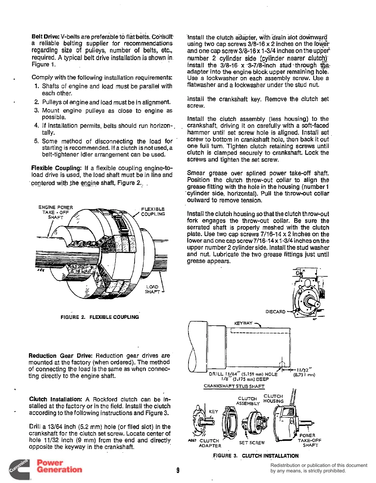
Clutch Installation:
A
Rockford clutch can be
in-
stalled at the factory or in the field. Install the clutch
according
to
the following instructions and Figure
3.
Drill a 13/64 inch
(5.2
mm) hole (or filed slot) in the
crankshaft for the clutch set screw. Locate center
of
hole 11/32 inch
(9
mm) from the end and directly
opposite the keyway in the crankshaft.
*
‘Install the clutch adapter, with drain slot downward
using two cap screws 3/8-16 x 2 inches on the
low&
and onecapscrew3/8-16~ 1-3/4inchesontheupper
number
2
cylinder side (Cylinder
nearer
~Iufck);
Install the 3/8-16. x ‘3-7/8‘inch stud .-through
t&:
adapter into the engine block upper remaining hole.
Use a lockwasher on each assembly screw. Use
a
flatwasher and a lockwasher under the stud nut.
Install the crankshaft key. Remove the clutch set
screw.
Install the clutch assembly (less housing) to the
crankshaft, driving it on carefully with a soft-faced
hammer until set screw hole is aligned. Install set
screw to bottom in Crankshaft hole, then back it out
one full
turn.
Tighten clutch retaining screws until
clutch is clamped securely to crankshaft. Lock the
screws and tighten the set screw.
Smear grease over splined power take-off shaft.
Position the clutch throw-out collar to align the
grease fitting with the hole in the housing (number
1
‘cylinder side, horizontal). Pull the throw-out collar
outward to remove tension.
Install the clutch housing
so
that
the
clutch throw-out
fork engages the throw-out collar. Be sure
the
serrated shaft is properly meshed with the clutch
plate. Use two cap screws 7/16-14 x
2
inches on the
lower
and
onecapscrew7/1&14~1-3/4inchesonthe
upper number
2
cylinder side. Install the stud washer
and nut. Lubricate the two grease fittings just until
grease appears.
DISCARD
f
n
I
n
KEYWAY
3
CRANKSHAFT STUB SHAFT
IIY
CLUTCH
CLUTCH
HOUSING
ASSEMBLY
TAKE-OFF
SHAFT
SET SCREW
A867
CLUTCH
ADAP‘IE
R
..
.
.FIGURE
3.
CLUTCH
INSTALLATION
9
Redistribution or publication of this document
by any means, is strictly prohibited.
Redistribution or publication of this document
by any means, is strictly prohibited.
 Loading...


