The overrunning clutch is packed in a special high
melting point grease and after its initial assembly,
needs no further lubrication. This clutch prevents the
engine from turning the starter motor at too high a
speed once it is started.
Do
not subject the overrun-,
ning clutch to grease dissolving or high temperature
cleaning methods. This may cause the clutch to lose
some or all of its grease.
If the pinion does not turn freely in the clutch in the
overrunning direction, or the clutch tends to slip in
the opposite direction, replace the assembly.
A
worn
clutch indicated by excessive looseness of the pinion
req u
i
res replacement.
Never attempt to repair or relubricate a defective clutch.
Pinion Clearance
The pinion clearance is adjusted by increasing or
decreasing the fiber washer thickness at the mount-
ing surface of the shift solenoid.
More washers decrease the clearance while less washers increase
the pinion clearance.
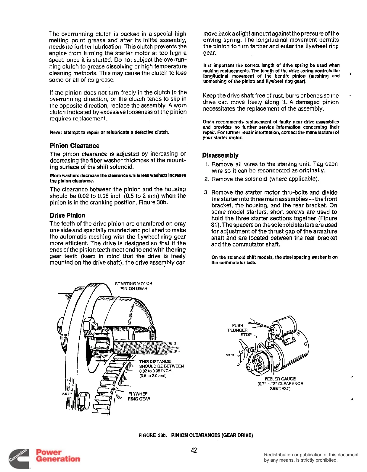
The clearance between the pinion and the housing
should be
0.02
to
0.08
inch
(0.5
to
2
mm) when the
pinion is in the cranking position, Figure 30b.
Drive
Pinion
The teeth of the drive pinion are chamfered on only
one side and specially rounded and polished to make
the automatic meshing with the flywheel ring gear
more efficient. The drive
is
designed
so
that if the
ends of the pinion teeth meetend toend with the ring
gear teeth (keep in mind that the drive is freely
mounted on the drive shaft), the drive assembly can
STARTING
MOTOR
flm
PINION
GEAR
SHOULD
BE BEMlEEN
0.02
to
0.08
INCH
move back aslight amount againstthe pressureof the
driving spring. The longitudinal movement permits
the pinion to turn farther and enter the flywheel ring
gear.
It is important the correct length of drive spring be used when
making replacements. The length of the drive spring controls the
longitudinal movement
of
the bendix pinion (meshing and
’
unmeshing of the pinion and flywheel ring gear).
Keep the drive shaft free of rust, burrs or bendsso the
drive can move freely along
it.
A
damaged pinion
necessitates the replacement of the assembly.
4
Onan recommends replacement of faulty gear drive assemblies
and provides no further service information concerning their
repair.
For
further repair information, contact the manufacturer
of
your starter motor.
Disassembly
1.
Remove all wires to the starting unit. Tag each
2.
Remove the solenoid (where applicable).
wire
so
it
can be reconnected as originally.
3.
Remove the starter motor thru-bolts and divide
the starter into three main assemblies- the front
bracket, the housing, and the rear bracket. On
some model starters, short screws are used to
hold the three starter sections together (Figure
31).The spacers on the solenoid starters are used
for adjustment of the thrust gap of the armature
shaft and are located between the rear bracket
and the commutator shaft.
On the solenoid shift models, the steel spacing washer is on
the commutator side.
FEELER
GAUGE
(0.7”
-
.12”
CLEARANCE
SEETEXT)
.
FIGURE
30b.
PINION
CLEARANCES
(GEAR
DRIVE)
42
Redistribution or publication of this document
by any means, is strictly prohibited.
Redistribution or publication of this document
by any means, is strictly prohibited.
 Loading...


