RCCK
Installation
SHAFT
GENERAL
The type of installation can affect the life of the
engine, the cost of operation and the frequency of
necessary service. Plan the installation carefully to
ensure the best performance.
DIMENSIONS
IN
INCHES
KEY
SIZE
1
DIAMETER LENGTH
Due to the great variety of uses, for the engine, these
installation instructions are typical and general in
nature. Use the installation recommendations given
as a general guide, improvising or altering as
necessary.
MOUNTING
There are several acceptable methods of mounting
the engine. Among factors to be considered are:
location, method of coupling the engine to the load,
type
of
foundation or support, etc. The engineshould
be mounted level if possible. Maximum operation
angle is
15'
sideways,
30'
front to rear
tilt.
If the
engine will operate at an angle, besure to re-mark the
oil level indicator to compensate for the
tilt.
Standard
Rockford Clutch
Gear
Reduction
VENT1 LATl ON
The engine must be provided with asupply of fresh air
for radiator cooling and for combustion.
Open Air Installation:
For installations where the
engine is operated outside, ventilation usually is no
problem. However, in protecting the engine from the
elements, be sure nothing obstructs the flow
of
air
around the engine.
1-1
I2
2-314
3/8
(38.10
mm)
(69.85
rnm)
(9.53
mm)
1-711
6
3-1
/2
318
(36.51
mm)
(88.90
rnrn)
(9.53
mm)
1-7/4
2-3/4
1 I4
(31.75
rnm)
69.85
rnm)
(6.35
mrn)
EXHAUST
Vent exhaust gas outside enclosure. Shield the line if
it
passes through a combustible wall or partition. If
turns are necessary, use sweeping type (long radius)
elbows. Increase one pipe size (from manifold outlet
size) for each additional
10
feet
(3
m) in length.
Locate the outlet away from the engine air intake.
Plan the exhaust system carefully.
Exhaust gases are poisonous!
CARBURETOR
AIR
INTAKE
Proper engine efficiency depends upon a supply
of
fresh air to the carburetor. Under special conditions,
it
may be necessary to move the air cleaner off the
engine, using a longer connection hoseas necessary.
For extreme dust or dirt conditions, install a special
heavy duty air cleaner.
FUEL SYSTEM
The engine uses a mechanical type fuel pump which
is mounted
on
top of the engine, adjacent to the
carburetor.
A
rubber fuel line connects the fuel pump
to the carburetor.
The fuel supply tank may be installed in any safe,
convenient location.
If
the tank is installed within the
engine enclosure, provide a vent line to theoutsideof
the enclosure. The top of the tank should be about
6
inches
(152
mm) below the carburetor, but not more
than
4
feet
(1.2
m) below the fuel pump.
,
.
The installation of a fuel filter between the fuel tank
and the fuel pump is recommended. Any fuel filter
should be fitted with a shutoff valve and should be
easily accessible for cleaning.
WARNING
Fuel leaks create fire and explosion
i
hazards which might result in severe
personal injury or death. Always use flexibk tubing
between engine and the fuel supply to avoid line
failure and leaks due to vibration. The fuel system
must meet applicable codes.
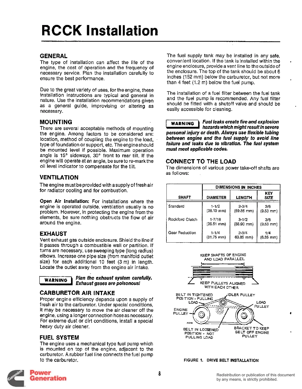
CONNECT TO THE LOAD
The dimensions of various power take-off shafts are
as follows:
KEEP SHAFTS OF ENGINE
AND LOAD PARALLEL
KEEP PULLEYS ALIGNED
WITH EACH OTHER
BELT IN TIGHTENED A/LER PULLEY
POSITION
-
PULLING
LOAD
-
BRACKET
TO
KEEP
BELT
OFF
ENGINE
BELT IN LOOSENED
POSITION
-
NOT
PULLING LOAD
PULLEY
FIGURE
1.
DRIVE BELT INSTALLATION
8
Redistribution or publication of this document
by any means, is strictly prohibited.
Redistribution or publication of this document
by any means, is strictly prohibited.
 Loading...


