I
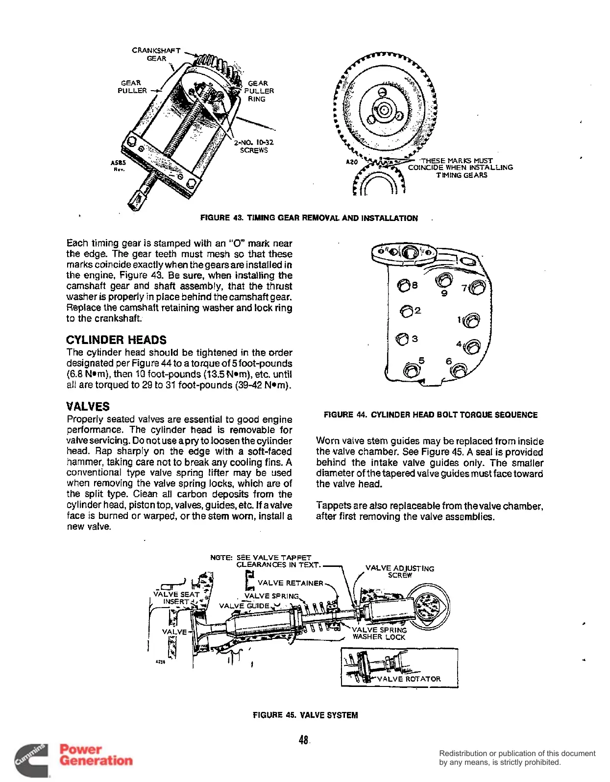
FIGURE 43.
TIMING
GEAR REMOVAL
AND
INSTALLATION
Each timing gear
is
stamped with an
"0"
mark near
the edge. The gear teeth must
mesh
so
that these
marks coincide exactly when thegears are installed
in
the
engine, Figure
43.
Be
sure,
when
installing the
camshaft gear and shaft assembly, that the thrust
washer
is
properly in place behind thecamshaft gear.
Replace the camshaft retaining washer and lock ring
to
the crankshaft.
CYLINDER HEADS
The cylinder head
should
be tightened
in
the order
designated per Figure 44to a torqueof 5foot-pounds
(6.8
Nom), then
10
foot-pounds (13.5N.m). etc. until
all
are torqued to
29
to
31
foot-pounds
(39-42
Nom).
VALVES
Properly seated valves are essential to good engine
performance. The cylinder head
is
removable for
vaiveservicing.
Do
not use apry to
loosen
the cylinder
head. Rap sharply on the edge with a soft-faced
hammer, taking care not
to
break any cooling fins.
A
conventional type valve spring litter may be used
when removing the valve spring locks, which are of
the split type. Clean all carbon deposits from the
cylinder head, piston top, valves, guides, etc.
If
avalve
face is burned
or
warped, or the stem
worn,
install a
new valve.
FIGURE
44.
CYLINDER
HEAD
BOLT
TORQUE SEQUENCE
Worn valve stem guides may be replaced from inside
the valve chamber. See Figure
45.
A
seal is provided
behind the intake valve guides only. The smaller
diameter of the tapered valve guides must face toward
the valve head.
Tappets are atso replaceable from thevalve chamber,
after first removing the valve assemblies.
NOTE
SEE VALVE
TAPPET
CLEARANCES
IN
TEXT
VALVE
RETAINE
CLEARANCES
IN
TEXT
VALVE
RETAINE
FIGURE
45.
VALVE
SYSTEM
48.
Redistribution or publication of this document
by any means, is strictly prohibited.
Redistribution or publication of this document
by any means, is strictly prohibited.
 Loading...


