Table of Figures
Figure 1: Scan Area ...................................................................................................................................... 4
Figure 2: Correct and Incorrect LED Aiming ................................................................................................. 5
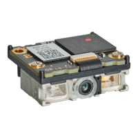
Figure 3: MEK-3100 Evaluation Board ......................................................................................................... 6
Figure 4: MEK-3100 Evaluation Board Kit .................................................................................................... 6
Figure 5: Opticon’s “Universal Config” .......................................................................................................... 7
Figure 6: Precautions for Sending Command Packets ................................................................................. 9
Figure 7: Transition Diagram in Fast Boot Mode ........................................................................................ 13
Figure 8: Mirrored Image Styles .................................................................................................................. 16
Figure 9: Mirrored Image Configurations .................................................................................................... 16
Figure 10: Creating 1D Menu Barcodes with Opticon’s “UniversalConfig.” ................................................ 18
Figure 11: Creating a 2D Menu Barcode with Opticon’s “UniversalConfig.” ............................................... 19
Figure 12: Data Character Transfer Format ................................................................................................ 21
Figure 13: No Handshake ........................................................................................................................... 22
Figure 14: BUSY/READY ............................................................................................................................ 23
Figure 15: RTS/CTS Data Transmission .................................................................................................... 23
Figure 16: CTS, TxD Signal Timing ............................................................................................................ 23
Figure 17: Modem RTS/CTS Data Transmission ....................................................................................... 24
Figure 18: ACK/NAK Transmission ............................................................................................................. 25
Figure 19: ACK/NAK Flowchart .................................................................................................................. 25
Figure 20: ACK/NAK No Response Flowchart ............................................................................................ 26
Figure 21: COM to HID Output Through WIME .......................................................................................... 31
Figure 22: Power Mode Transition .............................................................................................................. 37
Figure 23: Transition Time .......................................................................................................................... 41
Figure 24: USB Low Power Mode Communication Sequence ................................................................... 43
Figure 25: Recovery Example Using TRIGn Signal .................................................................................... 44
Figure 26: Recovery Example Using Commands ....................................................................................... 45
Figure 27: Recovery Example from Low Power Mode (USB) ..................................................................... 46
Figure 28: Power-On Timing ....................................................................................................................... 47
Figure 29: Power-Off Timing ....................................................................................................................... 48
Figure 30: Read Timing ............................................................................................................................... 48
Figure 31: Trigger Signal Control ................................................................................................................ 49
Figure 32: Start from TRIGn Signal End ..................................................................................................... 50
Figure 33: Start from TRIGn Signal Start .................................................................................................... 50
Figure 34: Command Trigger Control ......................................................................................................... 50
Figure 35: Command Trigger Control with Effective Read Time ................................................................ 50
Figure 36: Trigger Delay Timing ................................................................................................................. 51
Figure 37: GS1 Edit Feature in Opticon’s “UniversalConfig” ...................................................................... 56
Figure 38: Positive and Negative Barcode Images ..................................................................................... 57
Figure 39: Quiet Zone ................................................................................................................................. 57
Figure 40: Prefix/Suffix and Preamble/Postamble ...................................................................................... 84
Figure 41: Code Coordinates ...................................................................................................................... 89
Figure 42: Scan Time .................................................................................................................................. 90
Figure 43: Readable Positions in Central Reading ..................................................................................... 92
Figure 44: Unreadable Positions in Central Reading .................................................................................. 92
Figure 45: MDI-4100 and MDI-4150 Mechanical Drawing ........................................................................ 112
Figure 46: MDI-4100 and MDI-4150 Circuit Board ................................................................................... 113
Figure 47: MDI-4000 and MDI-4050 Mechanical Drawing ........................................................................ 114
Figure 48: DBM-4000 and DBM-4050 Decoder Board ............................................................................. 115
Figure 49: DBM-4000 and DBM-4050 Circuit Board ................................................................................ 115
Figure 50: FPC Cable ............................................................................................................................... 116