EasyManua.ls Logo

Opticon MDI-4100 - How to Switch to USB-HID; USB-HID Interface Signal

Opticon MDI-4100
139 pages
Print Icon
To Next Page IconTo Next Page
To Previous Page IconTo Previous Page
Loading...
MDI-4000 Series Serial Interface Manual
32
4.3.1 How to Switch to USB-HID
When you change the interface to USB-HID, the configuration change persists through a
firmware update.
Use one of these methods to change the serial interface to USB-HID:
Send this command:
[X.ZSU[X.ZZ2
Read this 2D menu barcode:
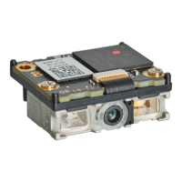
4.3.2 USB-HID Interface Signal
An IRISO Electronics Co., Ltd. 9681-12(12PIN) (bottom contact) equivalent connector is used.
No.
Name
Function
I/O
Conditions
State
Notes
1
TRIGn
Trigger
In
L: Start operation
H: No action
100kΩ pull up
on module
2
AIM/WAKEn
Recovery signal
from Low Power
state
In
L: Recover from
low power state
H: No action
100kΩ pull up
on module
Aiming control
signal in other
states than Low
Power
In
L: Aiming LED on
H: Aiming LED off
3
GR_LEDn
Good read LED
Out
L: LED on
H: LED off
100kΩ pull up
on module
EX_ILLUM
Control of an
external light
source.
Out
Configured
*1
L: External
Illumination On
H: External
Illumination Off
4
BUZZERn
Buzzer
Out
100kΩ pull up
on module
*2
5
POWERDWN
Indicates Low
Power state
Out
L: Normal state
100kΩ pull up
on module
6
RTS
Communication
control signal to
host system
Out
Put it to Open.
10kΩ pull up
on module
7
USB+
Communication
control signal
from host system
In/Out
100kΩ pull up
on module
8
TxD
Transmitted data
signal
Out
Put it to Open.
10kΩ pull up
on module
9
USB-
Received data
signal
In/Out
100kΩ pull up
on module
10
GND
System ground
11
VCC
Power input
In
3.3V or 5.0V
12
Reserve
In
N.C.
*1
When this is set, Good Read LED cannot be used.
*2
Tone and sound pressure are controlled by the pulse-width modulation (PWM) signal.

Table of Contents

Related product manuals