Installation
−12−
4.6 Installing the capacitor
Mount the capacitor securely using M4 screw (not provided).
Ø4.3 mm
(0.169 in.)
Note
•
Do not let the screw fastening torque exceed 1 N·m (8.8 lb-in) to prevent damage to the
mounting foot.
•
Install the capacitor apart from the motor. If it is located closer, the capacitor life may be
shortened due to the heat of the motor.
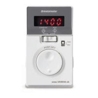
4.7 Installing an external potentiometer
When using an external potentiometer (supplied or sold separately:
PAVR-20KZ
), install it as shown in the gure.
Nut
Tightening torque:
0.45 N·m (3.9 lb-in)
Setscrew (M4)
Tightening torque:
0.4 N·m (3.5 lb-in)
• Reference mounting hole dimensions
[Unit: mm (in.)]
Ø3 (0.12)
7.5
±0.4 (0.3±0.02)
Ø10 (0.39)
Dial
Toothed washer
Dial plate
Mounting plate
Insulation sheet
Variable resistor
Soldering the variable resister terminals and the lead wires
Cover a heat-shrinkable tube over the soldered part to insulate.
Soldering condition: 235 °C (455 ˚F), less than 5 sec
Lead wire
Lead wire
Terminal
Heat-shrinkable tube
Solder
(Pass the lead wire through
the terminal hole and give it
two or three turns.)
DialVariable resistor
Refer to p.20 for connection of the external potentiometer.
 Loading...