Connection
−15−
5.4 Grounding
Be sure to ground a motor and speed controller using the Protective Earth Terminal and FG terminal, respectively.
Note
Be sure to ground the motor and speed controller to prevent them from being damaged by static
electricity. Static electricity may cause damage to the product if the Protective Earth Terminals are
not grounded.
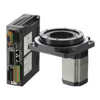
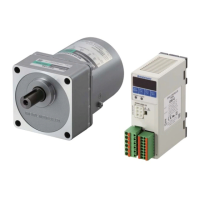
Grounding the motor
Ground close to the motor using the Protective Earth Terminal of the motor. Minimize the wiring length of the
ground cable.
Applicable crimp terminal: Insulated round crimp terminal
Terminal screw size: M4
Tightening torque: 1.0 to 1.3 N·m (8.8 to 11.5 lb-in)
Applicable lead wire: AWG18 (0.75 mm
2
) or thicker
4.8 (0.19) or less
Ø4.1 (0.16) or more
Note
Do not use screws other than the Protective Earth Terminal screw attached on the product.
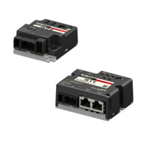
Grounding the speed controller
Connect the speed controller using the FG terminal of the CN1 (Main circuit connector).
5.5 Connecting the control DC power supply and I/O signals
Connect the control power supply and I/O signals to the CN4.
For the control DC power supply, use a power supply with reinforced insulation on its primary and secondary sides.
•
Applicable cable size: AWG24 to 18 (0.2 to 0.75 mm
2
)
•
Lead wire strip length: 10 mm (0.39 in.)
If crimp terminals are used, select the following terminals.
Manufacturer: PHOENIX CONTACT GmbH & Co. KG
Model: AI 0,25-10 [Conductor cross-sectional area: 0.14 to 0.34 mm
2
(AWG24)]
AI 0,34-10 [Conductor cross-sectional area: 0.14 to 0.34 mm
2
(AWG22)]
AI 0,5-10 [Conductor cross-sectional area: 0.40 to 0.65 mm
2
(AWG20)]
AI 0,75-10 [Conductor cross-sectional area: 0.65 to 0.82 mm
2
(AWG18)]
CN4 pin assignments
Pin No. Signal name Function
*
1
Description
1 +24 V
Control DC power supply Connect the 24 VDC power supply for control circuit.
2 0 V (GND)
3 IN0 [FWD]
The motor rotates in the forward direction while this signal
is being "ON."
*
2
4 IN1 [REV]
The motor rotates in the reverse direction while this signal
is being "ON."
*
2
5 IN2 [M0]
These signals are used to select the operation data
number.
6 IN3 [M1]
7 IN4 [ALARM-RESET] This signal is used to reset the alarm.
8 IN5 [FREE]
If the FREE input is turned "ON" while the motor is
operated, the motor will coast to a stop.
While the FREE input is being "ON," the motor will not
rotate even if the FWD input or REV input is turned "ON."
9 VH
External speed setting input
Connects when the rotation speed is set externally using
the external potentiometer or external DC voltage.
(Refer to p.20. )
10 VM
11 VL
12 N.C. − Not connected.
13 OUT0+
[SPEED-OUT]
12 pulses are output with each revolution of the motor
output shaft.
14 OUT0−
15 OUT1+
[ALARM-OUT]
This signal is output when an alarm generates
(normally closed).
16 OUT1−
*1
The signal in brackets [ ] is a function that is assigned at the time of shipment. Refer to p.31 for the signals that can be
assigned.
*2
The rotation direction varies depending on the gear ratio of the gearhead or the setting of the parameter. Refer to p.21 for
details.
 Loading...