4 SETUP INSTRUCTIONS
inc All rights reserved
27
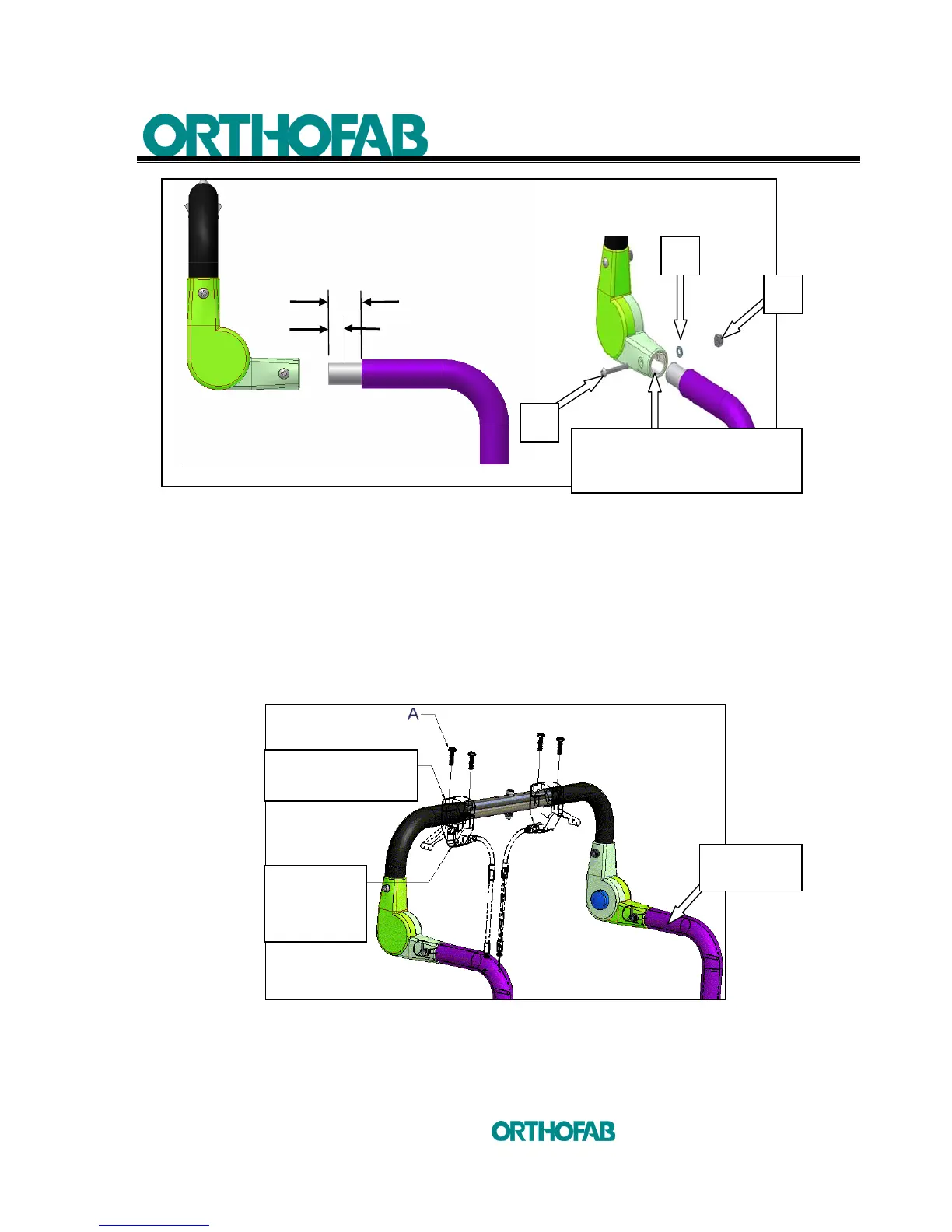
Figure 10-B.2 : Backrest handle and adjustable angle push handle assembly.
c) Handle assembly (see; figure 10-C) :
1. Remove the handles from the backrest post or from the cross bar and reinstall
them on the adjustable angle push handle;
2. Using a 4 mm Allen key, unscrew both (A)screws in the handle upper part.
Both parts (Upper and Bottom) are now separated;
3. Put back the handles without tighten (A) screws too much. Position the
handles in the way to be comfortable when using the push handle.
Figure 10-C : Handles assembly.
Cut 1½"
o
Fixation hole
at 1"
BACKREST
POST
A
B
C
INSERTION PART OF THE
ADJUSTABLE ANGLE PUSH
HANDLE.
HANDLE
UPPER PART
HANDLE
BOTTOM
PART



 To Next Page