4 SETUP INSTRUCTIONS
inc All rights reserved
26
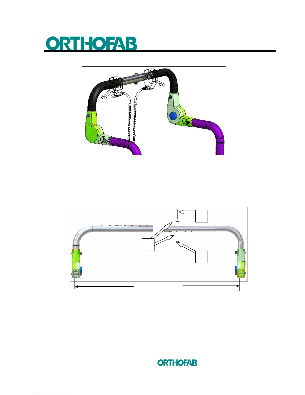
4.5.5 ADJUSTABLE ANGLE PUSH HANDLE
Figure 10-A : Adjustable angle push handle.
a) Width adjustment (see; figure 10-B.1) :
1. Insert the tubing one into the other and slide until you will reach the needed
width.
2. Use a Phillips screwdriver insert in the middle hole and tighten (A) screw,
(B) washers and (C) nut firmly. (Use a 3/8" wrench and a 5/32" Allen key).
Figure 10-B.1 : Width adjustment.
b) Installation of the adjustable angle push handle (see; figure 10-B.2) :
1. Cut out the end of the rubber handles on a length of 1 ½”;
2. Locate the insertion part of the adjustable angle push handle in the
backrest post, using a screwdriver to help. Put the (A) screw, (B)
washer and (C) nut and tighten firmly (Use a 3/8" wrench and 5/32"
Allen key).
Width –1"
A
C
B