Oxford Technical Solutions Ltd Page 25 of 110
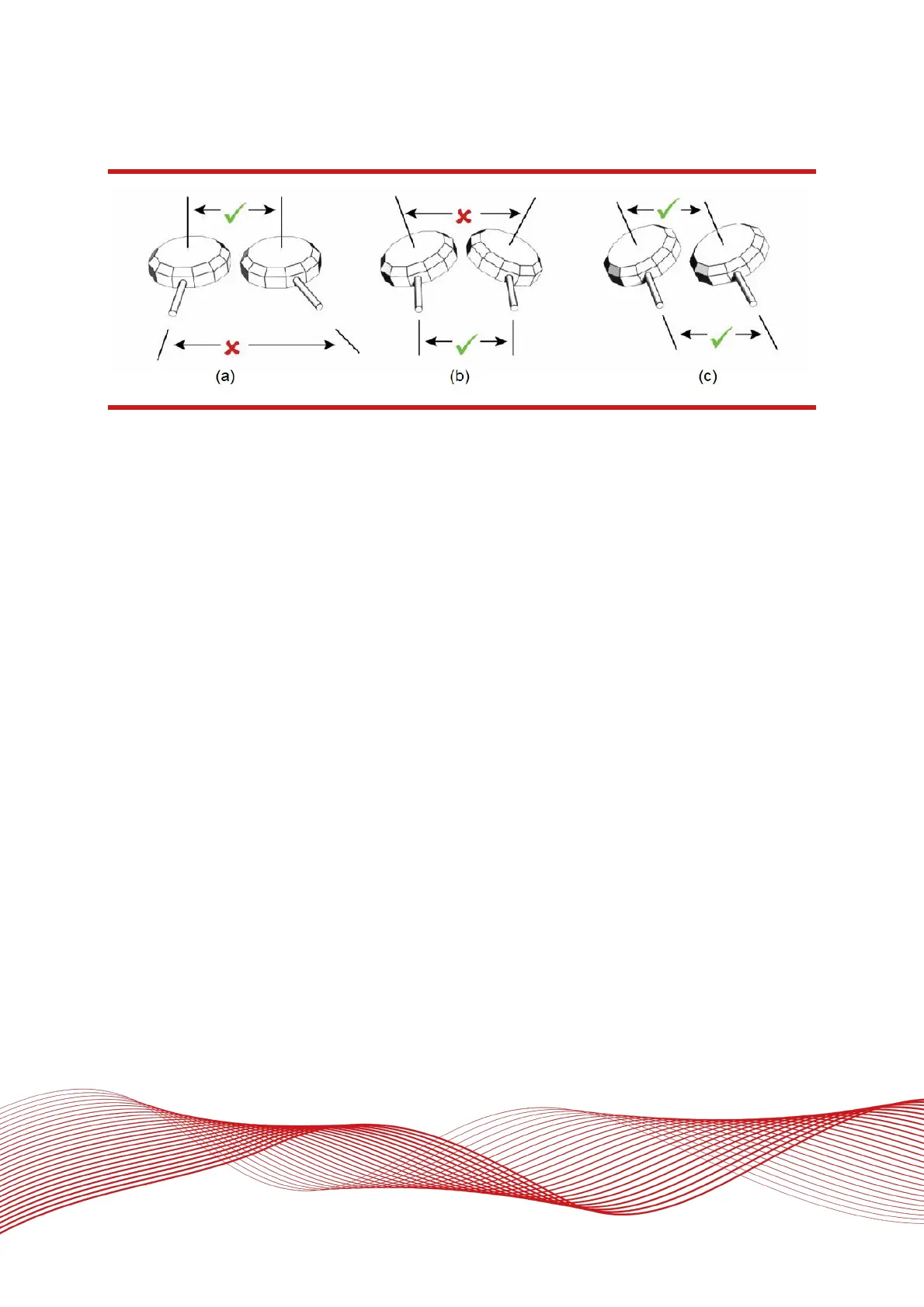
Figure 3: Dual antenna orientations
(a) The bases of the antennas are parallel, but the cables exit in different directions.
(b) The cables exit in the same direction but the bases of the antennas are not parallel.
(c) The bases of the antennas are parallel and the cables exit in the same direction. This configuration will achieve the best results.
Multipath affects dual antenna systems on stationary vehicles more than moving vehicles and it can lead to
heading errors of more than 0.5° RMS if the antennas are mounted poorly.
The Dual Antenna Roof Mount (DARM) can be used to provide an optimal antenna mounting solution for vehicles
with curved, glass or non-ferrous roofs where the above guidance can be difficult to achieve.
It is critical to have the RT mounted securely in the vehicle. If the angle of the RT can change relative to the
vehicle, then the dual antenna system will not work correctly. This is far more critical for dual antenna systems
than for single antenna systems. The user should aim to have no more than 0.05° of mounting angle change
throughout the testing. (If the RT is shock mounted then the RT mounting will change by more than 0.05°; this
is acceptable, but the hysteresis of the mounting may not exceed 0.05°).