Oxford Technical Solutions Ltd Page 51 of 110
IMU orientation tab
The IMU orientation tab is used to define the vehicle co-ordinate frame relative to the RT’s co-ordinate frame.
It is important to get the orientation correct as although settings entered on this page do not affect the
accuracy of the RT, if the outputs are not properly rotated to the vehicle frame then the measurements will
appear incorrect.
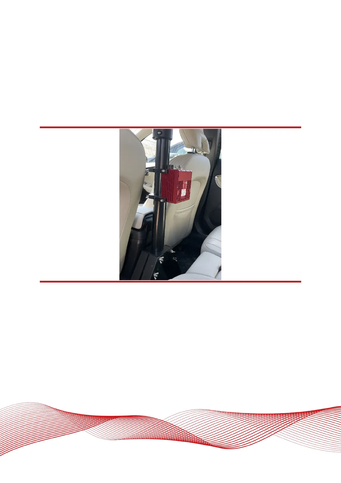
When using an RT-Strut, the orientation will need to be changed. Figure 22 shows an RT mounted on an RT-
Strut in a vehicle. In this configuration, the y-axis points left and the z-axis points forwards. Other
configurations are possible with the RT-Strut.
Figure 22: An RT device mounted on our RT-Strut
Use the Y axis points and the Z axis points box to specify which way the RT’s axes point in the vehicle. Figure
10 shows the RT axes’ directions. The IMU orientation tab of the configuration wizard, also has illustrations to
visualise the orientation of the RT in a vehicle based on the settings input. The advanced settings will change
to show the three rotations associated with orientation input, even when unavailable.