Oxford Technical Solutions Ltd Page 75 of 110
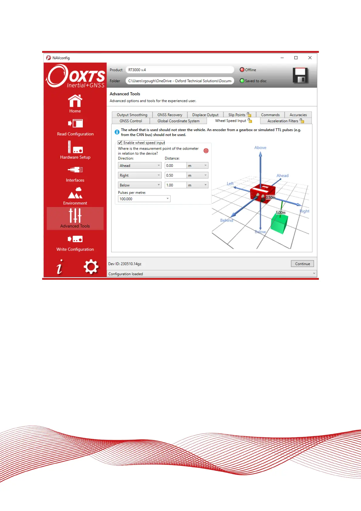
Figure 38: NAVconfig wheel speed Input tab in the advanced tools section
The distances from the measurement point on the RT to the measurement point of the wheel speed encoder
in the vehicle coordinate frame should be input. The directions can be selected from the dropdown lists. If the
wheel speed is from a prop shaft then the distance should be measured half way between the two wheels. The
illustrations in the image will change depending on the settings you choose, to help visualise the position of
the RT in relation the wheel speed sensor.
Measurements by default are made to an accuracy of 10 cm. Using higher precision for the measurement does
not improve the results. Using an accuracy figure worse than 20 cm will increase the drift of the RT. The
accuracy can be specified exactly in the Accuracies tab in the Advanced Tools section along with other
measurements such as antenna position.
Enter the pulses per metre of the wheel speed. A value that is accurate to 10% is sufficient unless you know
the figure more accurately. The RT will improve this scaling factor itself when GNSS is available. The Improve
Configuration utility can be used to apply a more accurate value calculated by the RT from a calibration run. If
this option is used then the RT should be allowed to recalibrate the scaling value occasionally to account for
tyre wear.