Oxford Technical Solutions Ltd Page 26 of 110
Operation
Front panel layout
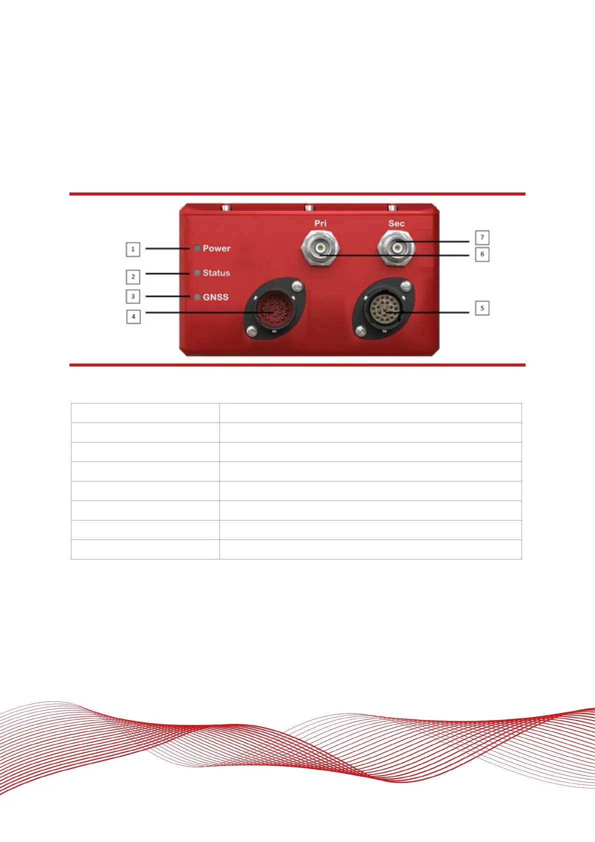
Figure 4 shows the layout of the RT3000 v4 front panel. Table 7 lists the parts of the front panel labelled in
Figure 4.
Figure 4: RT3000 v4 front panel layout
Table 7: RT3000 v4 front panel descriptions
1 Power LED
2 Status LED
3 GNSS LED
4 Main I/O user cable connector
5 Auxiliary user cable connector
6 Primary GNSS antenna connector
7 Secondary GNSS antenna connector
LED definitions
The LEDs on the connector panel provide information about the current system state, but it is not possible for
the LEDs to communicate everything the product is capable of measuring. Instead, they provide a snapshot of
the current status and are useful for at-a-glance checks without the need for a portable PC. The tables below
describe the behaviour of each LED.