Oxford Technical Solutions Ltd Page 34 of 110
Digital inputs and outputs
Table 15 describes each of the signals on the Digital I/O connector J5 of the main user cable. A more detailed
explanation of each signal can be found below.
Table 15: Digital I/O signals
J5-1 Digital 1 1 PPS output
Pulsed output from primary GNSS receiver, synchronised with the
transition of GPS seconds
J5-2 Digital 2 Trigger 1 User-selectable I/O (input/distance output/IMU sync output)
J5-3 Digital 3
Wheel speed
1A
Input for Hall-effect wheel speed sensor. When connecting a
quadrature sensor, this input is the A-channel
J5-4 Digital 4 Trigger 2 User-selectable I/O (input/distance output/IMU sync output)
J5-5 Digital 5
Wheel speed
1B
When connecting a quadrature wheel speed sensor, this input is for
the B-channel
1PPS output
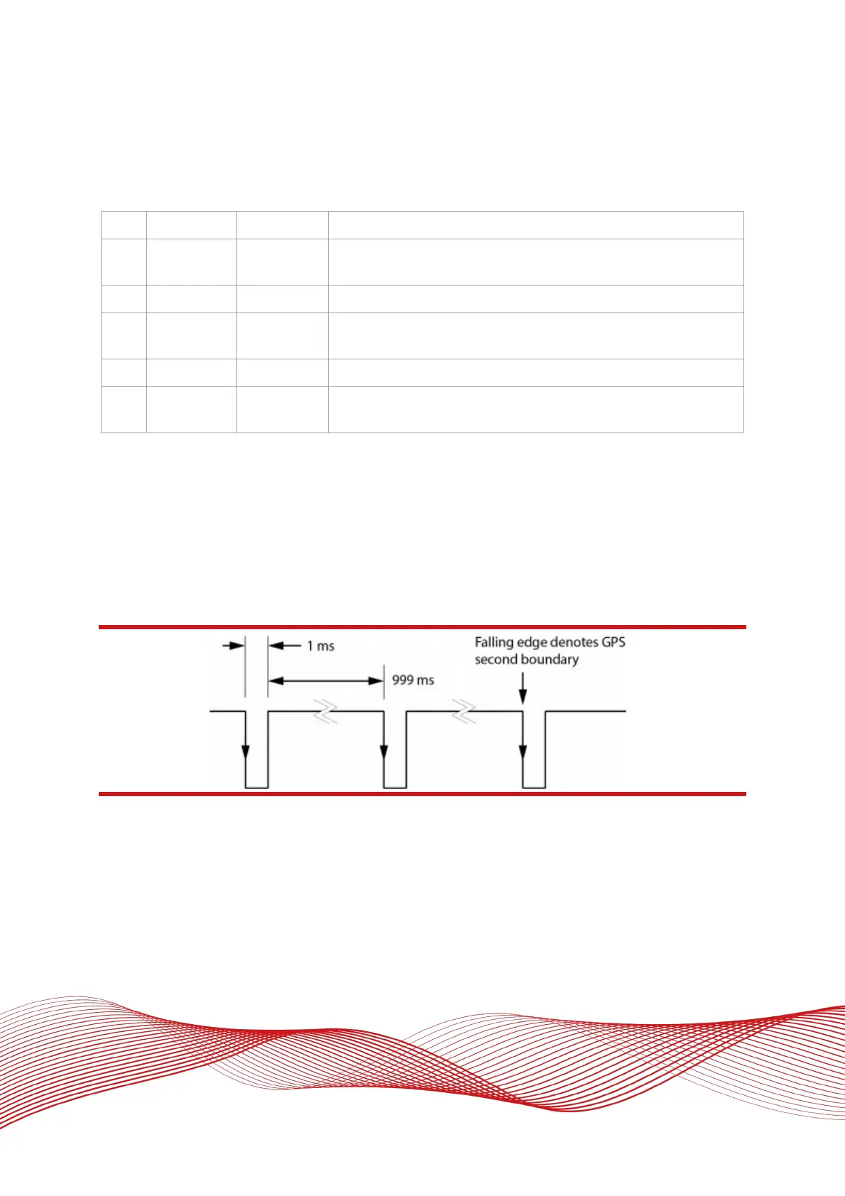
The 1PPS output is a pulse generated by the GNSS receiver. The output is active even when the GNSS receiver
has no valid position measurement. The falling edge of the pulse is the exact transition from one second to the
next in GPS time. The pulse is low for 1 ms, then high for 999 ms and repeats every second. The output is a
low-voltage CMOS output, with 0.8 V or less representing a low and 2.4 V or more representing a high. No more
than 10 mA should be drawn from this output.
Figure 8: 1PPS waveform
Trigger 1 and 2
Trigger 1 and Trigger 2 can be used to generate events within the RT for purposes of identifying external events,
or to output a time/distance-based signal for the purpose of driving external events. Both triggers are
independently configurable in the Options page of NAVconfig.
In input mode, the trigger waits for a signal from an external device such as a camera or switch. When a signal
is detected, a time-stamped measurement is generated by the INS in addition to the normal measurements