Oxford Technical Solutions Ltd Page 27 of 110
Table 8: Power LED states
Off There is no power to the system or the system power supply has failed.
Green Power is applied to the system.
Orange (Flashing) The system is powered and Ethernet traffic is present.
Table 9: Status LED states
Off The operating system has not yet booted. This occurs at start-up.
Red-green flash The system is asleep. Contact OxTS support for further information.
Red flash
The operating system has booted but the GNSS receiver has not yet output a
valid time, position, or velocity.
Red
The GNSS receiver has locked-on to satellites and has adjusted its clock to valid
time (1PPS output now valid). The INS is ready to initialise.
Orange
The INS has initialised and data is being output, but the system is not yet real-
time (the Kalman filter delay is a few seconds). It takes ~10 seconds for the
system to become real-time.
Green The INS is running and the system is real-time.
In the current versions of the software the strapdown navigator will not leave green and return to any other state. This may change in
future releases.
Table 10: GNSS LED states
Off GNSS receiver fault (valid only after start-up).
Red flash The GNSS receiver is active but has not yet determined heading.
Red The GNSS receiver has a differential heading lock.
Orange The GNSS receiver has a floating (poor) calibrated heading lock.
Green The GNSS receiver has an integer (good) calibrated heading lock.
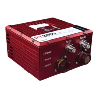
I/O connectors
There are two I/O user cable cable connectors on the RT3000 v4 front panel. The main connector is a male 22-
pin Deutsch AS612-35PA connector, marked with a yellow ring. The auxiliary connector is a female 22-pin
Deutsch AS612-35SN connector, marked with a red ring. Figure 5 shows the pin layout, applicable to both
connectors.