Oxford Technical Solutions Ltd Page 24 of 110
Do not install the RT where it is in direct sunlight as, in hot countries, this may cause the case
to exceed the maximum temperature specification.
Ensure that the RT is not installed near sources of significant heating or cooling as sudden
changes in ambient temperature can adversely impact satellite signal tracking.
Orientation and alignment
The orientation of the RT in the vehicle is normally specified using three consecutive rotations that rotate the
RT to the vehicle’s co-ordinate frame. The order of the rotations is:
1. Heading (z-axis rotation);
2. then pitch (y-axis rotation);
3. then roll (x-axis rotation).
It is important to get the order of the rotations correct.
The RT can be mounted at any angle in the vehicle as long as the orientation is described in the configuration.
This allows the outputs to be rotated based on the settings entered to transform the measurements to the
vehicle frame.
Antennas
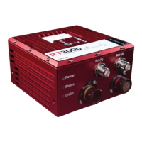
The RT3000 v4 has TNC connectors for the primary and secondary GNSS antennas. Antennas used with the RT
must at least be capable of tracking the GPS L1 signal for operation and additionally the GPS L2 signal for RTK
performance. Antennas capable of tracking L1 and L2 GLONASS signals, E1 and E5b Galileo signals, and B1 and
B2 Beidou signals should be used for optimal performance and improved reliability.
The RT3000 v4 is certified for use with GNSS antennas with a gain of <= 35 dB.
When using the INS in a dual antenna configuration, it is recommended to use the same type
of antenna with the same cable lengths for both the primary and secondary receivers.
Antenna placement and orientation
For optimal performance it is essential for the GNSS antenna(s) to be mounted where they have a clear,
uninterrupted view of the sky and on a suitable ground plane, such as the roof of a vehicle. They should be
mounted away from any potential sources of interference, such as LiDAR systems.
The antennas cannot be mounted on non-conducting materials or near the edges of conducting materials. If
the antennas are to be mounted with no conductor below them, then different antennas must be used. It is
recommended to mount the antennas at least 30 cm from any edge where possible.
For dual antenna systems, the secondary antenna should be mounted in the same orientation as the primary
antenna, as shown in Figure 3. The antenna baseline should also be aligned with one of the vehicle axes where
possible, either inline or perpendicular to the vehicle’s forward axis.

 Loading...