Oxford Technical Solutions Ltd Page 32 of 110
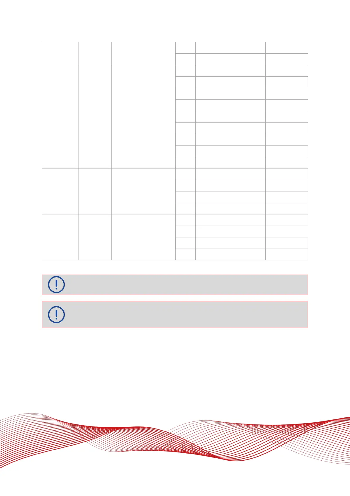
6 CAN ground J4-3
7 CAN+ J1-9
J5 Digital I/O 9-way female D-type
1 Digital 1 J1-11
2 Digital 2 J1-8
3 Digital 3 J1-15
4 Digital 4 J1-19
5 Digital 5 J1-5
6 Digital ground J1-18
7 Digital ground J1-18
8 Digital ground J1-18
9 Digital ground J1-18
J6 Ethernet RJ45
1 Ethernet transmit+ J1-20
2 Ethernet transmit- J1-13
3 Ethernet receive= J1-21
6 Ethernet receive- J1-14
J7 Power 4-way M12 male plug
1 Supply+ J1-1
2 Sleeved and made safe
3 Supply- J1-2
4 Sleeved and made safe
See Table 15 for Digital I/O signal details
Power lines should be correctly terminated and insulated and wired up with a fuse somewhere
between the unit and power source before being connected to a power source.
The CAN interface does not include a termination resistor. Appropriate termination must be
used, e.g. if used in a single device connection, a 120 Ω terminating resistor must be added
between the CAN+ and CAN- pins.