766
JAN 2006
Ver. 5.2
DP-3510/3520/3530/4510/4520/4530/6010/6020/6030
11.3.2.8. Power Supply System
11.3.2.8.1. Finisher / Saddle Assembly
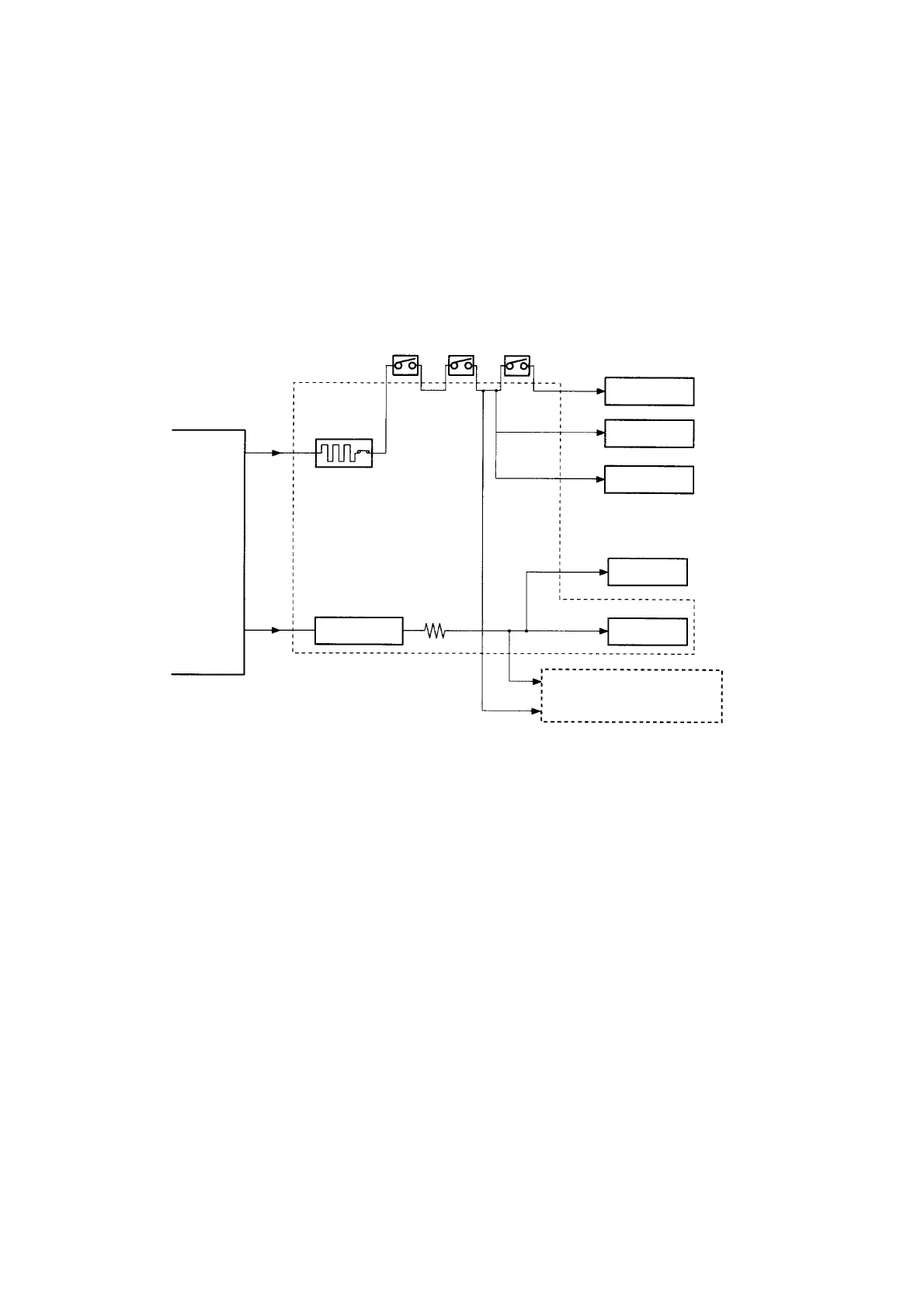
1. Outline
When the Host Machine is turned on, it supplies the Finisher Controller PCB with two channels of 24
VDC; one is for the motors and clutches, and the other is turned into 5 VDC by the Regulator IC (IC1)
of the Finisher Controller PCB for use by the sensors and ICs on PCBs.
If a punch unit (option) is installed, power is also supplied to the Punch Controller PCB. Some of 24
VDC used to drive motors is cut off when the Joint Switch (MS2), Front Door Switch (MS1), or Stapler
Safety Switch (MS3) is open.
Fig. 2-061 is a block diagram of the power supply system :
Fig. 2-064
2. Protective Mechanism
A circuit breaker (CB1) is monitored to protect the 24 VDC system sued to drive the motors against
overcurrent. The 24-V system used to drive the Feed Motor (M1), paddle motor (M2), and delivery
motor (M3) is equipped with a fuse that melts in the presence of overcurrent.
11.3.2.8.2. Punch Unit (Option)
1. Outline
When the Host Machine is turned on, the Punch Unit is supplied by the Finisher Controller PCB with
24-V and 5-V power.
The 24-V power is used to drive the motors, while the 5-V power is used by sensors and the ICs on the
Punch Controller PCB.
The 24-V power to the motors will be cut off when the Joint Switch (MS2) or the Front Door Switch
(MS1) of the Finisher Unit is open.
Host
Machine
Motor
Motor
Clutch
Sensor
Logic System
Punch Controller PCB
(Puncher Unit; Option)
Regulator IC
Circuit Breaker
(CB1)
Finisher
Controller PCB
(IC1)
24VP
24V
24V
24V
5V
5V
Joint Switch
(MS2)
Stapler Safety Switch
(MS3)
(MS1)
24VL

 Loading...


