797
JAN 2006
Ver. 5.2
DP-3510/3520/3530/4510/4520/4530/6010/6020/6030
Fig. 3-086
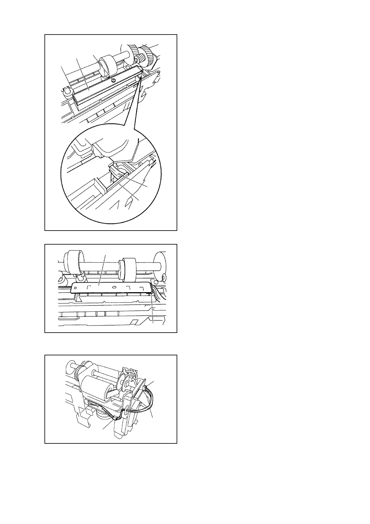
2-2. Removing the Photo Sensor PCB
(1) Remove the Punch Motor. (See 1-1.)
(2) Remove 1 Screw [1].
(3) Remove the Harness [3] from the Harness Guide
[2] on the PCB, then detach the PCB Cover [4].
Fig. 3-087
(4) Disconnect the Connector [5] to remove the
Photosensor PCB [6].
Fig. 3-088
2-3. Removing the LED PCB
(1) Remove the Waste Case.
(2) Disconnect Connector J1005 [1].
(3) Remove the Harness [3] from the Harness Guide
[2].
[1]
[3]
[2]
[4]
[6]
[5]
[1]
[3]
[2]

 Loading...


