22
7 Troubleshooting Guide
7.1. Troubleshooting Guide for F61 and/or F76
This section illustrates the checking procedures when upon detecting the error of “F61” and/or “F76” after power up of the unit. It is
for purpose of troubleshooting and checking in SMPS, D-Amp & Main P.C.B.
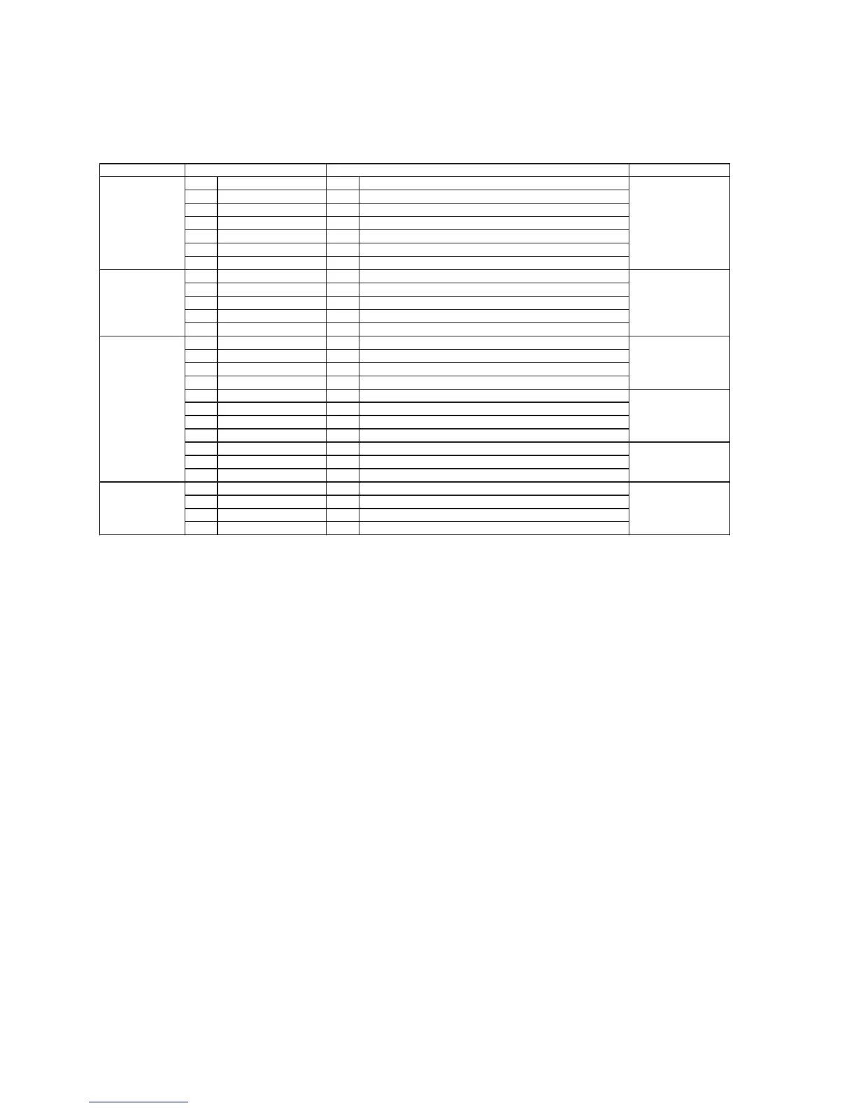
Symptom Remarks
Set cannot ON 1 AC Cord 1 AC Cord Faulty, Loose connection. Refer to
Section 7.2.1
Fig. 1. SMPS
P.C.B.
Refer to
Section 7.2.1
Fig. 1. SMPS
P.C.B.
Refer to
Section 7.2.2
Fig. 2. Main P.C.B.
Refer to
Section 7.2.1
Fig. 1. SMPS P.C.B.
Refer to
Section 7.2.1
Fig. 1. SMPS
P.C.B.
2 AC Inlet, P5701 2 P5701 solder crack, dry joint.
3 Fuse, F1 3 Fuse, F1 Open.
4 Photocoupler 4 PC5702/PC5799 solder crack.
PC5702, PC5799 Dry joint, short circuit, open circuit.
5 Switching IC, IC5701 5 IC5701 Faulty.
6 Switching IC, IC5799 6 IC5799 Faulty.
Set can ON 1 Speaker Output 1 Faulty speaker unit, Loose connection, Short. Refer to
Section 7.2.3
Fig. 3. D-Amp
P.C.B.
then F61
2 D-AMP circuit 2a D-AMP IC, IC5900 defective.
(DC voltage of +/-30V detected at speaker output)
Set can ON 1 Transformer T5701 1a Short circuit between Pin 14 and Pin 15.
then F76 1b Short circuit between Pin 15 and Pin 16.
1c Short circuit between Pin 16 and Pin 17.
2 DC-DC Circuit 2a Check cable wire connection between cable wire ZJ2701
(At Main P.C.B) & connector CN5802 (At SMPS P.C.B)
2b
Voltage Regulator IC (IC2701) &
Switching Regulator IC (IC2702) faulty.
3 Photocoupler 3 PC5720 solder crack,
PC5720 Dry joint, short circuit, open circuit.
Set can ON 1 Rectifier D5801 1a Improper contact between D5801 to Heatsink.
working normally Rectifier D5802 Improper contact between D5802 to Heatsink.
for some time 2 Thermistor TH5860 1b Set trigger temperature protection.
then F76
Possible Fault(s)Checking Items