26
7.3. D-Amp IC Operation & Control
D-AMP IC Operation & Control
1) D-AMP IC (C1AB0000497) was used for this model (AKX10).
2) Three control pins (signal send from micro-processor IC) were used to control the D-AMP IC
operation such as muting, standby and normal operation. They are described as below: -
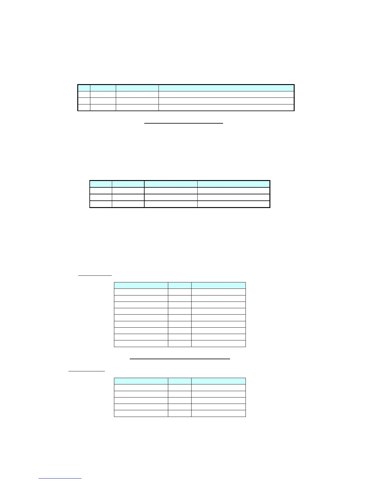
No Pin no Signal name Function
1 4 F_HOP Frequency Hop control.
2 6 MODE_DA Digital Amp On/Off control.
3 3 MUTE_F Digital Amp Muting control
Table 1: Digital AMP Pin Control.
Here is detailed description of the three control pins for the D-AMP IC
A) MODE_DA & MUTE_F were used to switch the D-AMP IC in the following muting status:
x L(Low/OFF): Standby / OFF
x H (High/ON): Operating or Mute
Below is the logic for the two pins used for the control of the D-AMP IC.
No MODE_DA MUTE_F Digital AMP IC mode status
1 L X OFF (0V)
2 H H Mute (2.5V)
3 H L Operating(5V)
Table 2: Digital AMP IC Mode Status.
Note: Standby/OFF condition of D.AMP IC is available / activated only during the following
event: Switching of Frequency Hoping, power off and start up (when the unit is undergoing
the transition from standby to normal operation mode)
B) F_HOP is used to control the D-AMP operation to avoid interference with AM source by
controlling the frequency source used. It will switch from one frequency to the other, depending on
the tuned AM frequency.
For 9 KHz Step
AM Band Frequency F_HOP Switching Frequency
522 ~ 558 L 301
567 ~ 639 H 350
648 ~ 855 L 301
864 ~ 945 H 350
954 ~ 1152 L 301
1161 ~ 1242 H 350
1251 ~ 1449 L 301
1458 ~ 1539 H 350
1548 ~ 1629 L 301
Table 3: F_HOP Control during 9 kHz Step
For 10 KHz Step
AM Band Frequency F_HOP Switching Frequency
520 ~ 560 L 301
570 ~640 H 350
650 ~ 860 L 301
870 ~ 950 H 350
960 ~ 1160 L 301