79
17 Schematic Diagram Notes
• This schematic diagram may be modified at any time
with the development of new technology.
Notes:
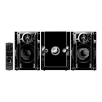
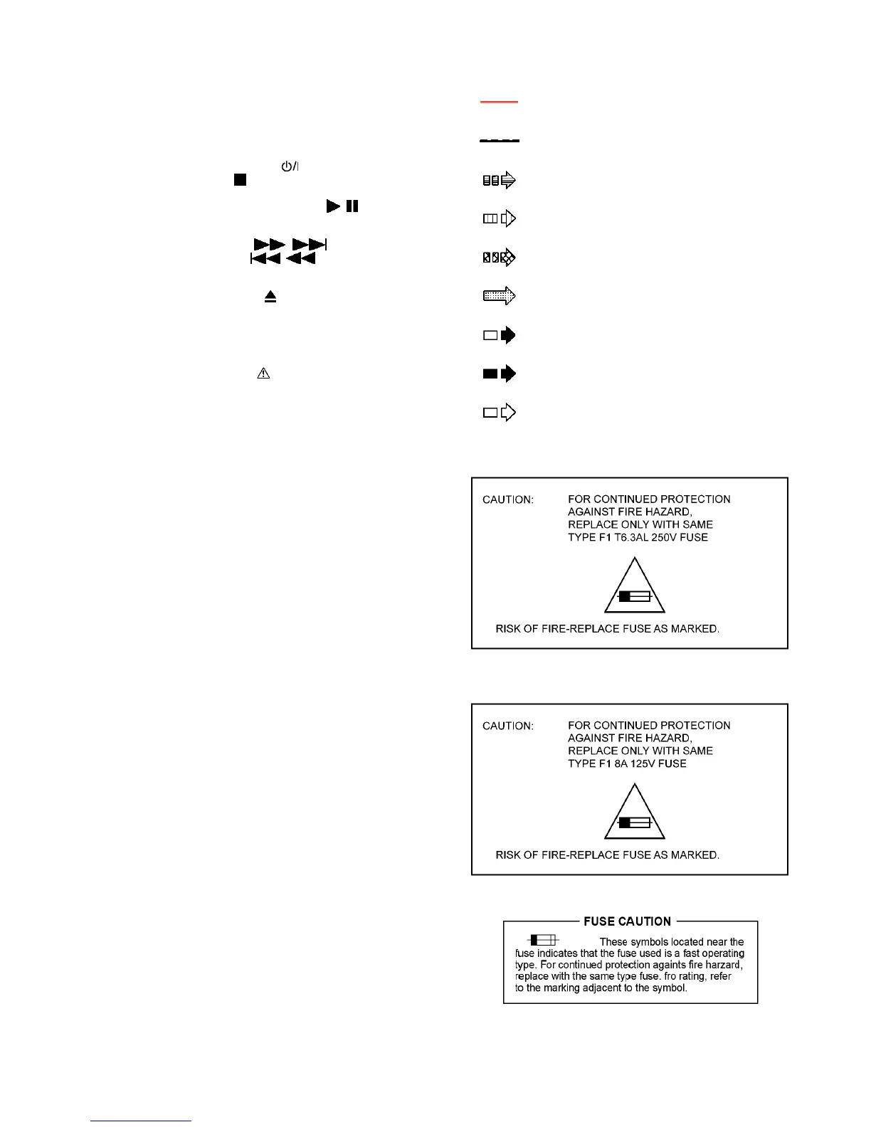
• Important safety notice:
Components identified by mark have special characteris-
tics important for safety.
Furthermore, special parts which have purposes of fire-retar-
dant (resistors), high quality sound (capacitors), low-noise
(resistors), etc are used.
When replacing any of components, be sure to use only
manufacturer’s specified parts shown in the parts list.
• In case of AC rated voltage Capacitors, the part no. and val-
ues will be indicated in the Schematic Diagram.
AC rated voltage capacitors:
For PN only:
C5701, C5703, C5704, C5705, C5708
For PH only:
C5701, C5703, C5704, C5705, C5706, C5707. C5708
• Resistor
Unit of resistance is OHM [Ω] (K=1,000, M=1,000,000).
• Capacitor
Unit of capacitance is µF, unless otherwise noted. F=Farads,
pF=pico-Farad.
• Coil
Unit of inductance is H, unless otherwise noted.
•
*
REF IS FOR INDICATION ONLY.
• Voltage and signal line
• For PH only
• For PN only
S5701: Voltage ADJ switch (For PH only).
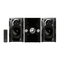
S6001:
Power switch ( ).
S6002:
Stop ( -DEMO) switch.
S6003: AUX Switch
S6004:
USB Play/Pause (USB / ) switch.
S6005: D.BASS switch.
S6006: Manual EQ (MANUAL EQ) switch.
S6007:
Forward ( / ) switch.
S6008:
Rewind ( / ) switch.
S6009: Album + switch.
S6010: Album - switch.
S6011:
CD switch ( ).
S6012: FM/AM switch.
VR6001: Volume Jog.
VR6002: Track Jog.
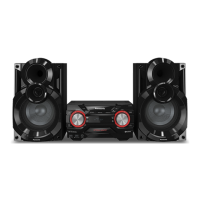
: +B signal line
: -B signal line
: CD Audio input signal line
: AUX input Audio signal line
: Audio output signal line
: USB signal line
: FM/AM signal line
: AM signal line
: FM signal line