61
11 Service Position
Note: For description of the disassembly procedures, see
the Section 9.
11.1. Checking and Repairing of
Main P.C.B.
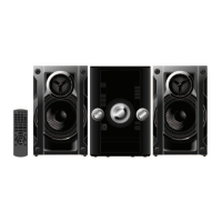
Step 1 Remove Top Cabinet.
Step 2 Main P.C.B. can be checked & repaired at its original
position.
11.2. Checking and Repairing of D-
Amp P.C.B.
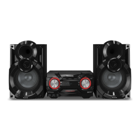
Step 1 Remove Top Cabinet.
Step 2 D-Amp P.C.B. can be checked & repaired at its original
position.
11.3. Checking and Repairing of
Panel P.C.B.
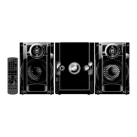
Step 1 Remove Top Cabinet.
Step 2 Remove Front Panel Assembly.
Step 3 Attach 17P FFC to the connector (CN2709) on Main
P. C .B ..
Step 4 Attach 22P FFC to the connector (P901) on USB
.P.C.B..
Step 5 Panel P.C.B can be chacked & repaired as diagram
shown.
 Loading...