48
11 Service Position
Note: For description of the disassembly procedures, see
the Section 10.
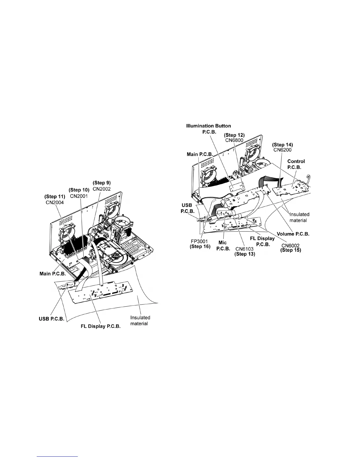
11.1. Checking of FL Display P.C.B.,
Control P.C.B., Volume P.C.B.,
Mic P.C.B. and USB P.C.B.
Step 1 Remove Top Cabinet.
Step 2 Remove Front Panel Unit.
Step 3 Remove FL Display P.C.B..
Step 4 Remove Illumination Button P.C.B..
Step 5 Remove Control P.C.B..
Step 6 Remove Volume P.C.B..
Step 7 Remove USB P.C.B..
Step 8 Remove Mic P.C.B..
Step 9 Attach 10P FFC at a connector (CN2002) on the Main
P. C.B . .
Step 10 Attach 11P Cable at a connector (CN2001) on the
Main P.C.B..
Step 11 Attach 30P FFC at a connector (CN2004) on the Main
P. C.B . .
Step 12 Attach 2P Cable at a connector (CN6800) on the Illu-
mination Button P.C.B..
Step 13 Attach 8P Cable at a connector (CN6103) on the Mic
P. C. B ..
Step 14 Attach 12P Cable at a connector (CN6200) on the
Control P.C.B..
Step 15 Attach 30P FFC at a connector (CN6002) on the FL
Display P.C.B..
Step 16 Attach 5P Wire at the connector (FP3001) on Main
P. C. B ..
Step 17 FL Display P.C.B., Control P.C.B., Volume P.C.B., Mic
P.C.B. and USB P.C.B. can be checked as diagram shown.