49
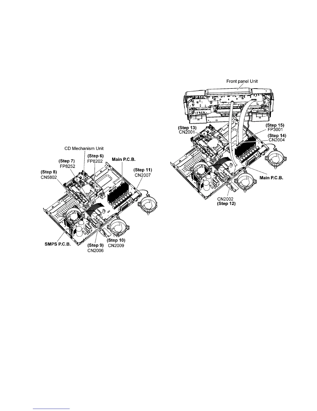
11.2. Checking of Main P.C.B. (Side
B)
Step 1 Remove Top Cabinet.
Step 2 Remove Front Panel Unit.
Step 3 Remove Rear Panel.
Step 4 Remove CD Mechanism Unit.
Step 5 Remove Main P.C.B..
Step 6 Attach 24P FFC at the connector (FP8202) on the Main
P. C. B ..
Step 7 Attach 10P FFC at the connector (FP8252) on the Main
P. C. B ..
Step 8 Attach 13P Cable at the connector (CN5802) on the
SMPS P.C.B..
Step 9 Attach 2P Wire at the connector (CN2006) on the Main
P. C. B ...
Step 10 Attach 2P Wire at the connector (CN2009) on the Main
P. C. B ..
Step 11 Attach 2P Wire at the connector (CN2007) on the Main
P. C. B ..
Step 12 Attach 10P FFC at a connector (CN2002) on the Main
P. C .B ..
Step 13 Attach 11P Cable at a connector (CN2001) on the
Main P.C.B..
Step 14 Attach 30P FFC at a connector (CN2004) on the Main
P. C .B ..
Step 15 Attach 5P Wire at the connector (FP3001) on Main
P. C .B ..
Step 16 Side B Main P.C.B. can be checked as diagram shown.