63
14 Schematic Diagram
14.1. Schematic Diagram Notes
• This schematic diagram may be modified at any time
with the development of new technology.
Notes:
• Important safety notice:
Components identified by mark have special characteris-
tics important for safety.
Furthermore, special parts which have purposes of fire-retar-
dant (resistors), high quality sound (capacitors), low-noise
(resistors), etc are used.
When replacing any of components, be sure to use only
manufacturer’s specified parts shown in the parts list.
• In case of AC rated voltage Capacitors, the part no. and val-
ues will be indicated in the Schematic Diagram.
AC rated voltage capacitors:
C5700, C5701, C5702, C5703, C5704, C5705, C5707,
C5708
• Resistor
Unit of resistance is OHM [Ω] (K=1,000, M=1,000,000).
• Capacitor
Unit of capacitance is µF, unless otherwise noted. F=Farads,
pF=pico-Farad.
• Coil
Unit of inductance is H, unless otherwise noted.
•
*
REF IS FOR INDICATION ONLY.
• Voltage and signal line
S5701: Voltage Selector switch.
S6000: Memory 2 switch.
S6001: Memory 3 switch.
S6002: Memory 4 switch.
S6003: Memory 1 switch.
S6004: Memory 5 switch.
S6005: Memory 6 switch.
S6006: DJ switch.
S6100: CD switch.
S6101: Radio/EXT-IN switch.
S6102: Stop ( ) switch.
S6103: Memory switch.
S6104: USB switch.
S6105:
Play/Pause ( / ) switch.
S6106: Memory Rec switch.
S6107: CD Open/Close switch.
S6200: Manual EQ switch.
S6201: Album/Track switch.
S6202: BASS switch.
S6203:
Power ( ) switch.
S6204: Latin/Preset EQ switch.
S6205: Superwoofer switch.
S6206:
Forward ( / ) switch.
S6207: Rewind ( / ) switch.
S6208: USB Rec switch.
S6800: Illumination switch.
VR6100: Volume Jog.
VR6200: Control Jog.
VR6300: Mic Jog.
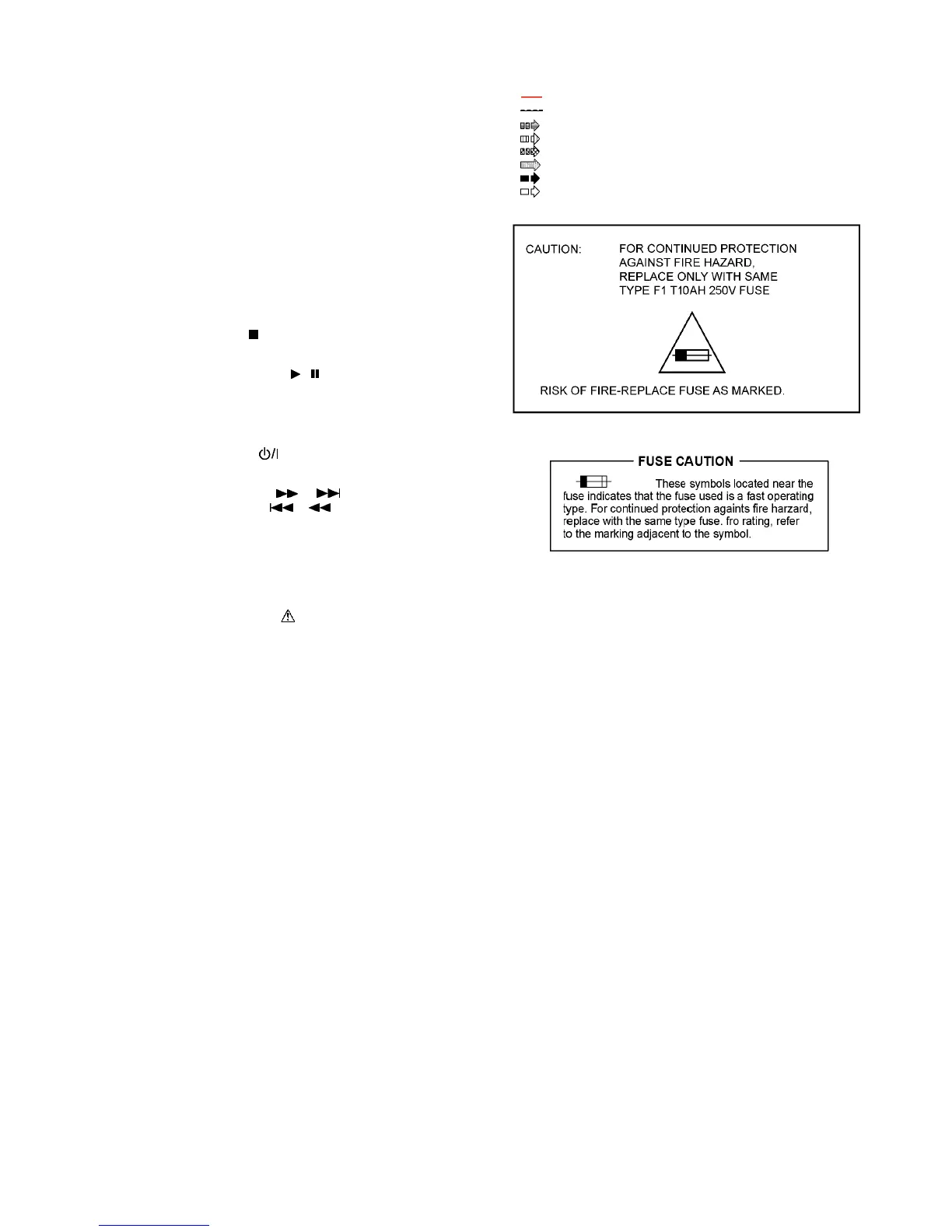
: +B signal line
: -B signal line
: CD Audio input signal line
: Mic/Tuner/Music Port/AUX input signal line
: Audio output signal line
: USB signal line
: AM signal line
: FM signal line