BA_PH_690-100_EN_10-22.docx
• Level unevenness of the floor by means of the stand adjusting screws (see next section 7.3).
Dispose of the packaging material in an environmentally friendly way!
7.3 Levelling with a Spirit Level
Caution: Ensure that all four feet are firmly on the floor, evenly loaded and the machine is
levelled with a spirit level.
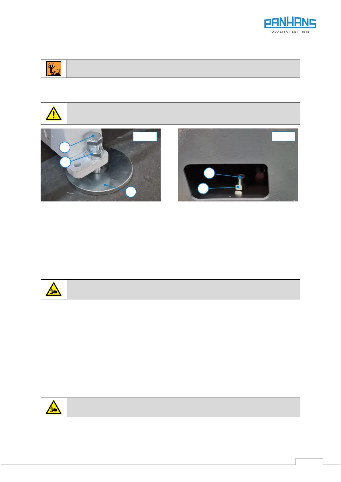
Figure 11: Levelling screws at the rear (normal case)
Figure 12: Front levelling screws (exceptional case)
When setting up the machine, it must be properly aligned with a machine spirit level (0.1 mm/ 1 m). For this
purpose, the machine has two adjustable feet with corresponding set screws (S) on the rear side ( Figure 11)
and two round plates (U) as a base. In the normal case, the front of the machine stands flush on the two ped-
estals. Level here only in exceptional cases (very uneven floors).
7.3.1 Procedure in the Normal Case
1. Before setting the machine down, lower it only close enough to the ground so that the two plate feet (U)
shown in Figure 11 can be placed centred under the screws (S).
Caution: Crushing hazard for hands and feet when lowering & setting down the machine!
2. Now lower the machine completely until it is centred on the plate feet with both screws (S).
3. To align with the spirit level, it is usually sufficient to adjust only the rear screws (S).
4. An open-end spanner SW22 is required for adjustment. First loosen the lock nuts (K) and
then adjust the height with the set screws (S) until the machine is evenly levelled.
7.3.2 Procedure in the Exceptional Case
1. If levelling cannot be achieved with the two rear feet, it must be assumed that the installation site has a
very uneven surface.
2. Only in this exceptional case are the front adjusting screws (see Figure 12) necessary for levelling.
However, these are only accessible after the front cover plate is removed.
3. Before adjusting, raise the machine on the front side so far that the two round plates (U) can also be placed
here centred under the adjusting screws (S).
Caution: Crushing hazard for hands and feet when lowering & setting down the machine!
4. Then loosen the four lock nuts (K) shown in Figure 12 and Figure 11 and adjust the height on all four
screws (S) until the machine is evenly level.