BA_PH_690-100_EN_10-22.docx
16.9 Power Feeder 76
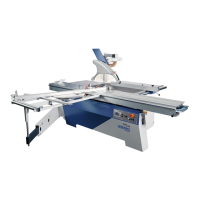
The circular saw power feeder 76 (Art. No. 2078) is the ideal addition to your sliding table saw. It ensures
additional safety and ergonomic working when cutting battens, planks, window scantlings and other work-
pieces made of solid wood. It is simply pushed onto the rip fence holding block (1) via the guide rail instead of
the standard rip fence rail and fixed via the clamping lever.
To prevent an interruption of the emergency stop chain, this option is only available in
combination with the option "Machine Socket" (Art. No. 4211, see
19.6).
For power supply, the machine plug is simply plugged into the optional machine socket.
Figure 69: Power feeder 76
Handwheel for height adjustment
Rotary switch ON / OFF / FEED RATE
(0 = OFF | 1 = 13 m/min | 2 = 26 m / min)
Stop plate for cutting width adjustment
Housing with rollers and protective cover
Features:
• With adjustable pick-up profile, 3 rollers and 2 feed rates
• Quick adjustment of the workpiece height via handwheel
• With suction port for dust-free working
• With rail for mounting height of 18 - 40 mm
• Integrated electrical magnet system to prevent tipping
• Tool-free quick assembly/disassembly on the rip fence
instead of the conventional standard aluminium profile
• Optimum view of the workpiece due to transparent,
swivelling protective cover
• Ergonomic work when cutting battens
• Power supply 400 V / 50 Hz (including machine plug)
Technical Specifications:
16.9.1 Mounting the Power Feeder
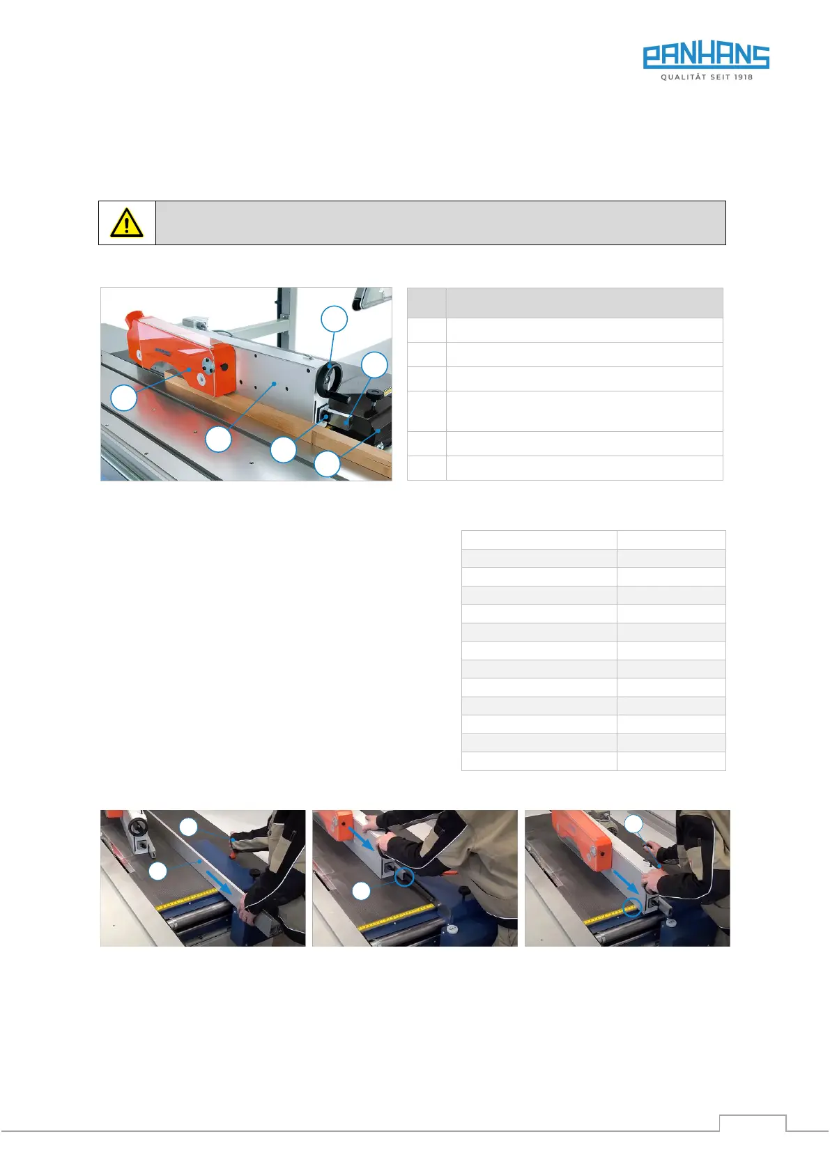
Figure 70: Mounting the power feeder
1. Release the lever (2) and pull
out the standard stop rail (4).
2. Push the power feeder
onto the rail (S).
3. Pull back to above the mm
scale and clamp with lever (2).
4. The cutting width (min. 25 mm) is set manually via the millimetre scale on the table.
Workpieces < 25 mm cannot be machined as they are too narrow for the centre roller.
5. Set the height of the feeder to the thickness of the workpiece and lower it approx. 3 mm to apply pressure.