BA_PH_690-100_EN_10-22.docx
16.4.2 Super Gehrfix I Operation
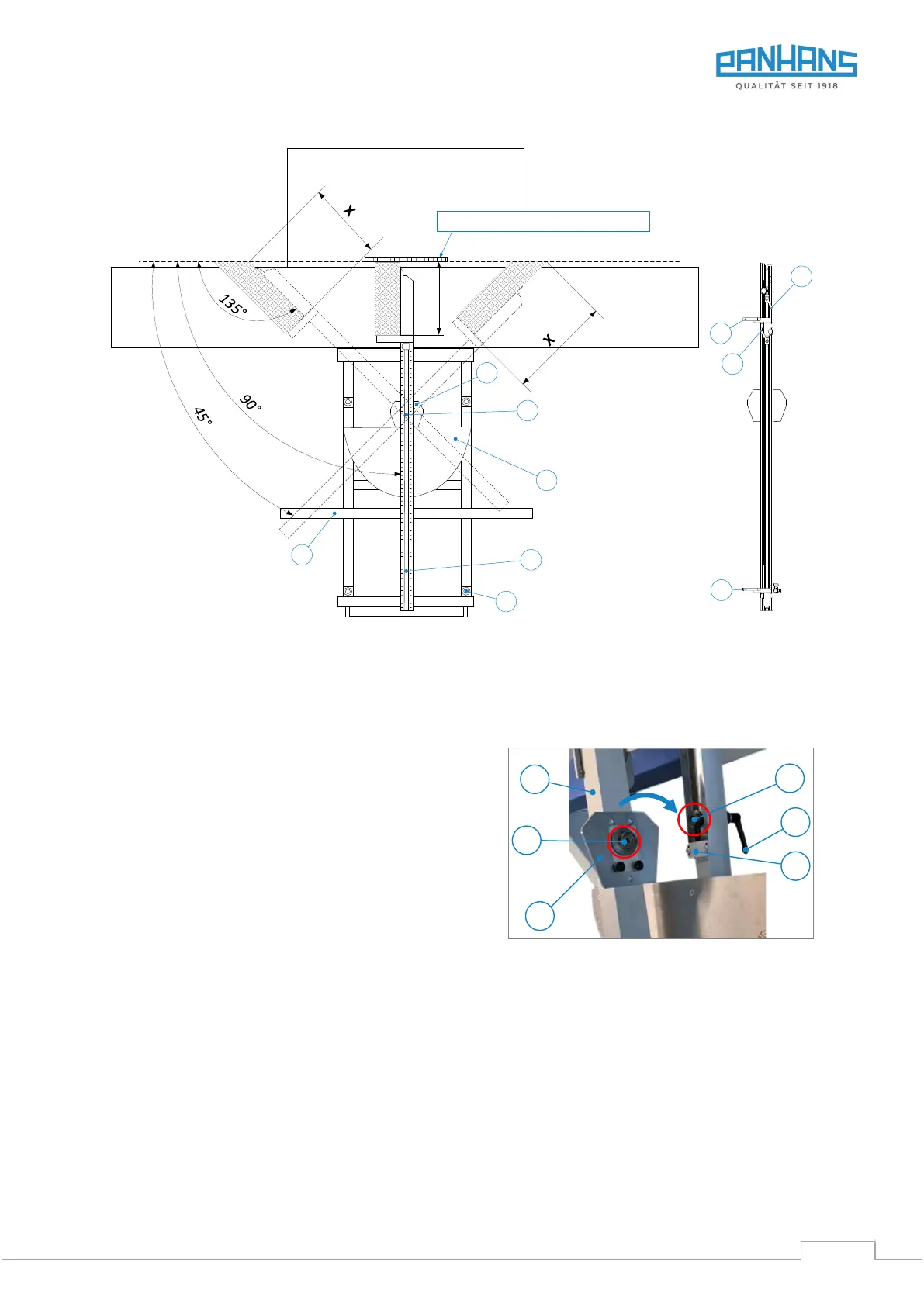
Figure 60: Super Gehrfix I overview
16.4.3 Attach Cross-Cut Fence
The crosscut fence is mechanically connected to the Super Gehrfix I via the locating pin (2), which is located in
the slotted hole for the length compensation.
The procedure is very simple:
• Loosen clamping lever (1) and push the locating bolt
(2) in the direction of the stop plate (P) as shown in
Figure 60 and Figure 61.
• Now place the cross-cut fence (L) on the cross slide
so that the locating pin (2) can be inserted into the
receptacle (X) on the underside of the stop plate (3).
• Then tighten the clamping lever (1) again.
Figure 61: Attach cross-cut fence
16.4.4 Set Length > 1885 mm
• Loosen flip stop (A) with (S1), set to 1885 mm using magnifying glass and clamp with (S1).
• Loosen flip stop (B) with (S2), move to the desired position and clamp with (S2).
16.4.5 Set Angle to 90 Degrees
For 90° cuts, the cross-cut fence (L) can be used in different positions:
• Via the fixing points (F) on the left or right of the cross slide. To do this, simply release clamping lever
(1) lift off the cross-cut fence (L) completely and insert it into the desired fixing points (F).
• Via the grid scale of the Super Gehrfix I (procedure see section 16.4.6).
X
45° 135°
Saw blade thickness = 3.2 mm
L
1
Lever below
(hidden view)
4
3
F
(4 x)
5
X
45° 135°
Sägeblattdicke = 3,2 mm
L
1
Hebel unterhalb
(Ansicht verdeckt)
4
3
F
(4 x)
5
A
S1
S2
B