MY19-P073_1.0_09.11.2018
111
Table of figures
Table of figures
Figure 1: Type plate, example, 15
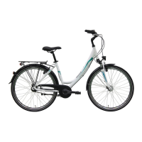
Figure 2: Bicycle viewed from the right; Pegasus Solero SL used as
example, 25
Figure 3: Detailed view of bicycle from rider position, example 1, 26
Figure 4: Detailed view of bicycle from left, example 2, 26
Figure 5: Detailed view of the stem, example of stem which can be
set without tool, 27
Figure 6: Components of the wheel, example of front wheel, 28
Figure 7: Bicycle without suspension (1) and with suspension (2)
when riding over an obstacle, 29
Figure 8: Example showing Suntour fork: The stem and handlebars
are fastened to the fork shaft (1). The wheel is fastened to
the quick release axle (6). Other elements: The
compression setting (2), crown (3), Q-Loc (5), dust
seal (6), fork end for quick release (7), stanchion (8) and
spring (9), 30
Figure 9: Rim brake components with details; Magura HS22 used
as an example, 31
Figure 10: Rim brake locking lever, closed (1) and open (2), 32
Figure 11: Bicycle brake system with a disc brake, example, 32
Figure 12: Brake system with a back-pedal brake, example, 33
Figure 13: Diagram of mechanical drive system, 35
Figure 14: Fastening the transport securing device, 38
Figure 15: Fully inserting the axle, 43
Figure 16: Tightening the axle, 43
Figure 17: Pushing the quick release lever into the axle, 44
Figure 18: Tightening the securing screw, 44
Figure 19: Tightening the inserted axle, 45
Figure 20: Tightening the axle, 45
Figure 21: Pushing the axle into the hub, 47
Figure 22: Tightening the axle, 47
Figure 23: Pushing the quick release lever into the axle, 48
Figure 24: Securing the lever, 48
Figure 25: Perfect position for the clamping lever, 49
Figure 26: Adjusting the quick release clamping force, 49
Figure 27: Open and closed flange, 51
Figure 28: Pushing the quick release in, 51
Figure 29: Adjusting the clamping, 52
Figure 30: Closing the quick release, 52
EN_MY19-P073_1.0_31.08.2018_Pegasus Fahrrad MY19_Inhalt.book Page 111 Friday, November 9, 2018 4:59 PM