COM
1 2
out2out1
C
1 2
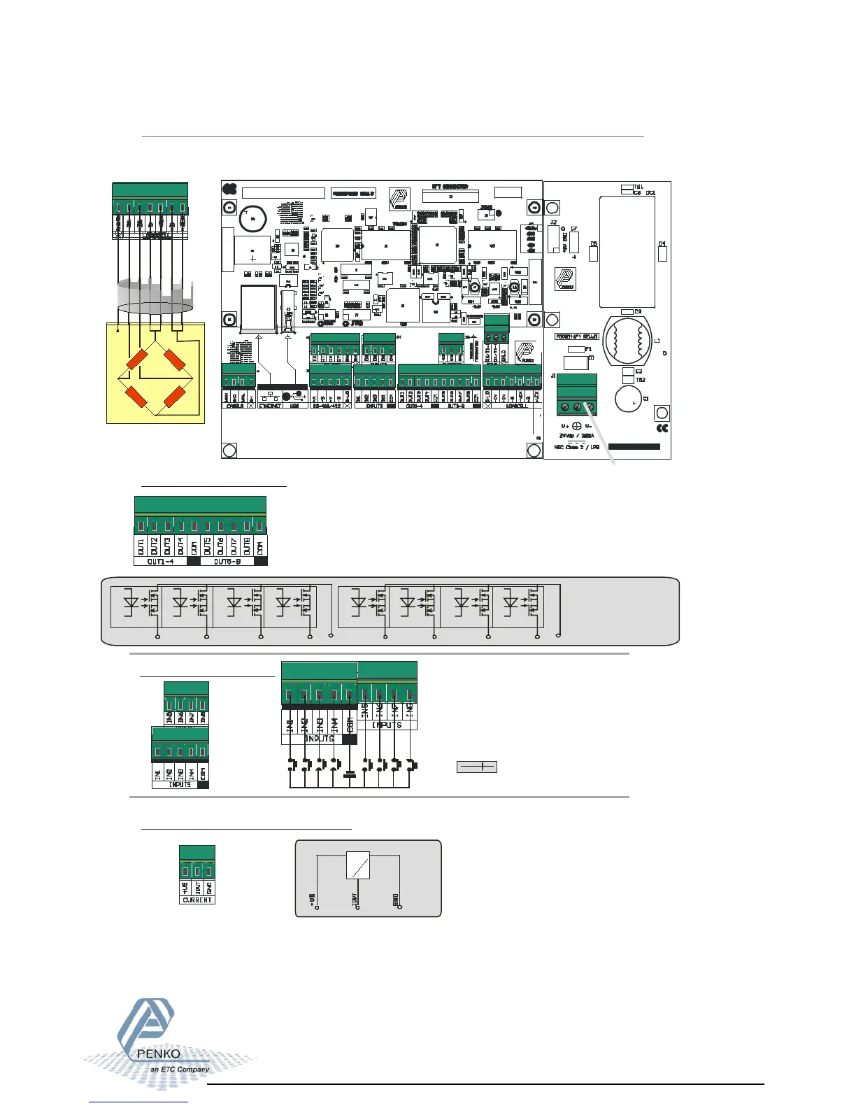
COMMON FOR OUTPUTS
-0Vac or 0Vdc
-24Vac or 24Vdc
Common max.35V \ 0,5A
3
4
Out4Out3
3 4
C
OM
5 6
out6out5
C
5 6
7 8
Out8Out7
7 8
Digital inputs 1-8
Digital outputs 1-8
-
+
18-28 VDC
+
-
WIRING CONNECTIONS:
LOADCELL(S), IN/OUTPUTS & POWER SUPPLY
Input 1 can be used as:
or
as
(max. counter input speed 5000Hz)
a normal input
a counter input
- SIGN
AL
SHIE
LD
- EXCIT
ATION
- SENSE
+ EXCI
TATION
+ SE
NSE
+SI
GNAL
1 2 3 4 C 5 6 7 8
Analog output mA (option)
G
rou
nd
fo
r o
utpu
t
an
d s
upp
ly
+Cur
ren
t
16 Bit Analog output
A
D
+Suppl
y
FLEX 2100Indicator/Controller:
Power supply
for analog output
18-30Vdc
LB
LF1S028
0317M
DC POWER SUPPLY VERSION
This product is intended to be supplied
by a Class 2 or Limited Power Source,
rated 10.8 - 31.2 Vdc, 0.65A@24Vdc.
- SI
GNAL
SHIELD
- E
XCITATION
- S
ENSE
+ EX
CITATIO
N
+
SENSE
+S
IGNAL