SMART I/O User’s Manual
©1996 PEP Modular Computers GmbHMarch 12, 1996 Page 4 - 19
4
Chapter 4 Digital Modules
4
4.2 SM-DOUT1
4.2.1 Introduction
The SM-DOUT1 provides eight optoisolated 24V DC (typ.) digital outputs
arranged in 2 independent groups. The maximum output switching fre-
quency is limited to 1 kHz (square wave) with the output in the ON state
when the system issues a logical ‘0’. The maximum continuous output
supply current is limited to 500mA (resistive loads) and provision has been
made to cater for inductive loads. The user interface is realized by 8 yellow
LEDs (1 per output channel) which illuminate when the output is ON.
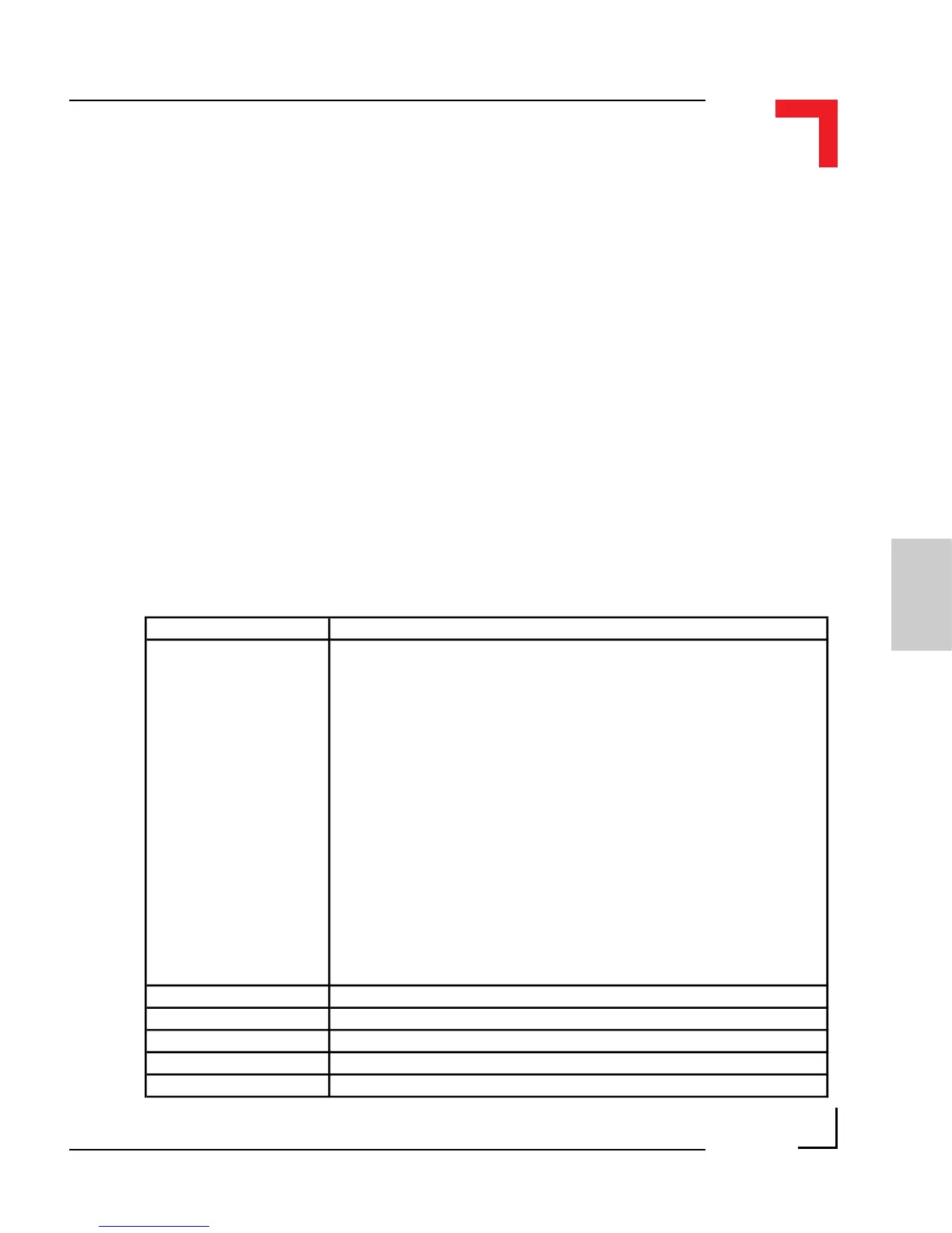
4.2.2 Specifications
Isolation 2.5 kV optoisolated from the system
Output
8 Digital Channels
2 Independent Groups
High-Side Switch (Common Vcc)
500mA Continuous Current (per
channel)
Inductive Load Protection (clamp
diode)
Power ON/OFF Protection
Overvoltage Protection
Output Voltage
Switch ON Delay (resistive)
Switch OFF Delay (resistive)
: 90V/10µs (35V)
: 24V DC
: 3µs (at 24V)
: 130µs (at 24V)
Max. Frequency
Output ON
Output OFF
Outputs after Reset
: 1 kHz square
wave
: Intern. Logical '0'
: Intern. Logical '1'
: OFF
Front Panel Yellow LEDs ON when the output is ON
Power Consumption 5mW (min.), 270mW (max.)
Temperature Range Standard (0°C to +70°C), Extended (-40°C to +85°C)
Module Weight 70g
ID Byte $10, read by the SPI Interface