SMART I/O User’s Manual
©1996 PEP Modular Computers GmbHMarch 12, 1996 Page 5 - 11
5
Chapter 5 Analog Modules
5.1.5.2 Output Circuitry
The digital to analog converter (DAC) section consists of a twin output 12-
bit DAC with external (on-board) 10.0V reference and an operational
amplifier for unipolar/bipolar outputs.
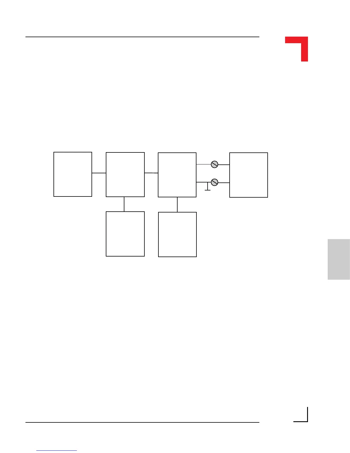
Figure 5.1.5.2: SM-DAD1 Output Schematic Diagram
Load
-10V .. +10V
0 .. +10V
AGND
VOUTx
Output
Amplifier
Uni-/Bipolar
Switch
(J4/J5)
DAC
Ref
System
Interface
The DAC is a complete dual 12-bit multiplying DAC without the need for
external trimming. Bipolar/unipolar mode is selected via jumpers J4 and J5
which allow both output channels to be configured separately.
It should be noted that in bipolar mode, the power-up condition is not glitch
free. Therefore it is suggested that the connected load be switched a short
time later to provide enough time for the DAC to initialize.