SMART I/O User’s Manual
March 12, 1996
©1996 PEP Modular Computers GmbH
Page 2 - 16
Chapter 2 SMART-BASE
The full-duplex description may be found in the SMART-I/O Advanced
User’s Guide.
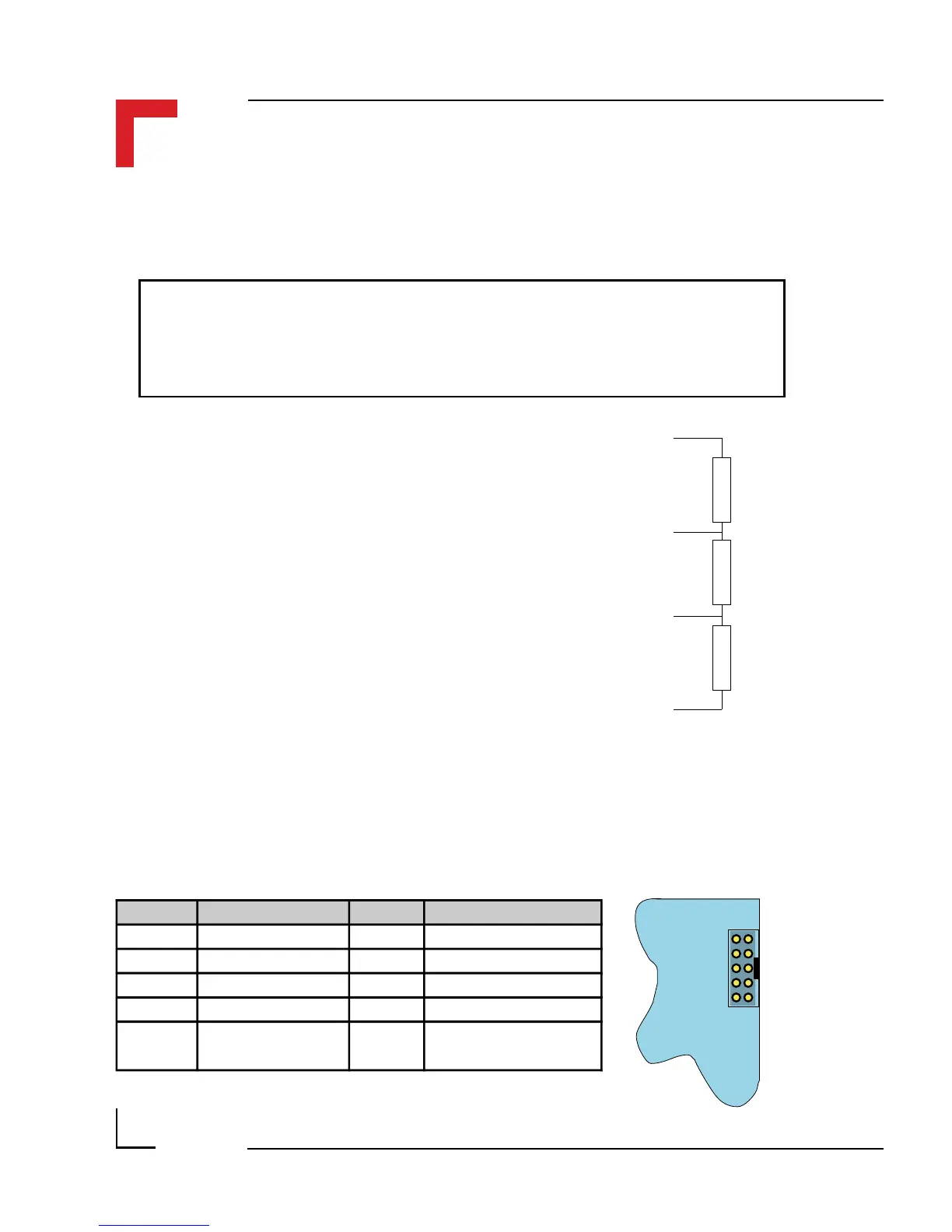
There is no internal line termination as laid down in DIN 19245 Part 1
and must be performed externally.
Note
ST7
Pin 1 Pin 2
Pin 9 Pin 10
SMART-BASE
2.5.7 SPI Connector (ST7)
The SPI connector is a 2x5 standard pinrow connector, located on the right-
hand side of the SMART-BASE to enable easy connection of the SMART-
EXT module using a flat ribbon cable connection.
The line termination is achieved as shown in
the figure. Assuming a power supply voltage
of +5V emanating from the PROFIBUS
connector (pin 6), the following resistor
values are recommended.
R
t
150Ω ± 2%, min 0.25W
R
U
390Ω ± 2%, min 0.25W
R
d
390Ω ± 2%, min 0.25W
Pin Nr. Signal Pin Nr. Signal
1 System VCC 2 Serial RxD
3 System VCC 4 Serial TxD
5 Serial Ext. Select 6 Serial CLK
7 System GND 8 Reset
9 System GND 10
Serial Ext. Interrupt
(Controller I/O IRQ4)
R
u
= 390Ω
R
t
= 150Ω
R
d
= 390Ω
Aux. +5V, 90mA
T/RxD +
T/RxD -
Aux. GND