SMART I/O User’s Manual
©1996 PEP Modular Computers GmbHMarch 12, 1996 Page 3 - 7
3
Chapter 3 SMART-EXT
3.4.1 SMART Module Piggyback Connectors
There are two sets (one for each module) of SMART-Module piggyback
connectors present on the SMART-EXT, each divided into two sets of 2x8
standard pin rows. The communication to these connectors is achieved in
part via the 10-wire flat-band interface cable and directly by the MCU.
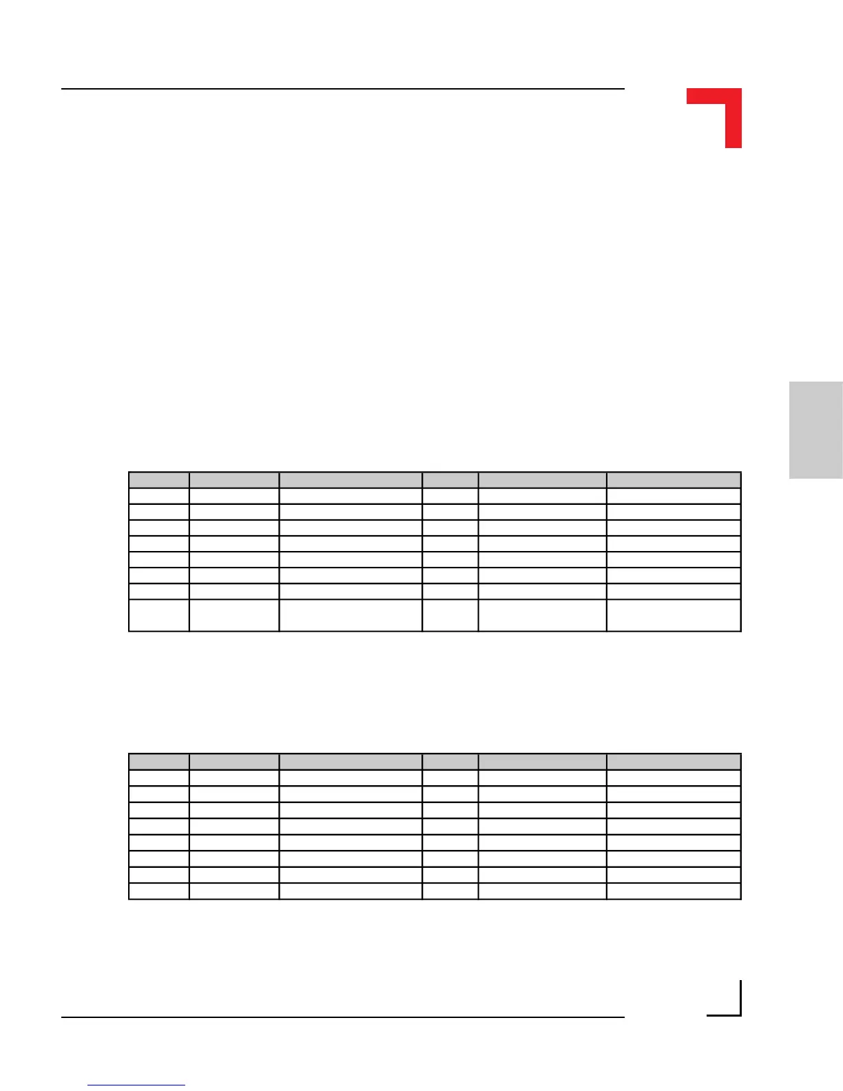
Pinouts digital side (ST1 and ST3)
Refer to figure 3.4.0.1 for the correct location of these pin-row connectors.
Slot A from 68HC05C4 MCU port A (ST1)
Pin Nr. Signal Description Pin Nr. Signal Description
1 PA1 Port A Pin 1 2 PA2 Port A Pin 2
3 PA3 Port A Pin 3 4 PA4 Port A Pin 4
5 PA5 Port A Pin 5 6 PA6 Port A Pin 6
7 PA7 Port A Pin 7 8 PA8 Port A Pin 8
9 System GND GND 10 Serial RxD RxD to SM-BASE
11 System VCC System +5V VCC 12 Serial TxD TxD from SM-BASE
13 CS-SLOTA Chip Select A 14 Serial CLK CLK from SM-BASE
15 Reset Power ON/OFF Reset 16 Slot A Interrupt line
INT4 to the
I/O Controller
Pin Nr. Signal Description Pin Nr. Signal Description
1 PB1 Port B Pin 1 2 PB2 Port B Pin 2
3 PB3 Port B Pin 3 4 PB4 Port B Pin 4
5 PB5 Port B Pin 5 6 PB6 Port B Pin 6
7 PB7 Port B Pin 7 8 PB8 Port B Pin 8
9 System GND GND 10 Serial RxD RxD from SM-BASE
11 System VCC System +5V VCC 12 Serial TxD TxD from SM-BASE
13 CS-SLOTB Chip Select B 14 Serial CLK CLK from SM-BASE
15 Reset Power ON/OFF Reset 16 Slot B Interrupt line Interrupt PI/T (H4)
Slot B from 68HC05C4 MCU port B (ST3)