SMART I/O User’s Manual
March 12, 1996
©1996 PEP Modular Computers GmbH
Page 6 - 8
Chapter 6 Communications Modules
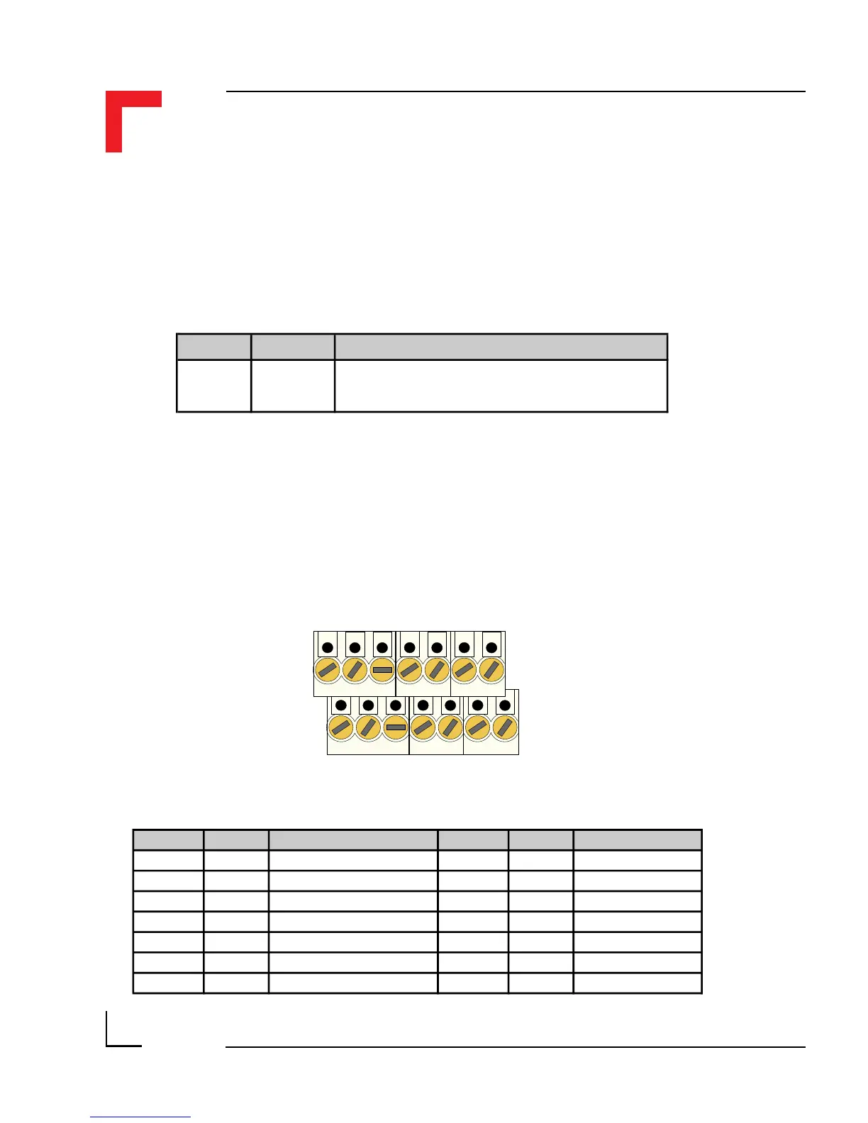
Pin Nr. Signal Description Pin Nr. Signal Description
1 TxD Transmit Signal 2
N/C
No Connection
3 RxD Receive Signal 4
N/C
No Connection
5 DTR Data Terminal Ready 6
N/C
No Connection
7 CTS Clear to Send 8
N/C
No Connection
9
N/C
No Connection 10
N/C
No Connection
11
N/C
No Connection 12
N/C
No Connection
13 GND Ground 14 GND Ground
Pin 1
Pin 2
Pin 13
Pin 14
6.1.7 Pinouts
Screw Terminal Pinouts
The following shows the pinout/signal relationship for the SM-RS232 when
connected to a particular screw terminal block.
6.1.6 Configuration
Jumper J1 - EEPROM Protection
Jumper Settings Description
J1
set EEPROM is not hardware write protected
open EEPROM is hardware write protected