SMART I/O User’s Manual
March 12, 1996
©1996 PEP Modular Computers GmbH
Page 3 - 8
Chapter 3 SMART-EXT
Pinouts process side (ST2 and ST4)
Refer to figure 3.4.0.1 for the correct location of these pin-row connectors.
Slots A and B (ST2 and ST4)
The PC board connections to the screw terminals are capable of absorbing a
continuous current of up to 3A each. However, pins 13 and 14 can support up
to 6 Amps.
3.4.2 Parallel I/O Screw Terminals (SCRA and SCRB)
The screw terminal blocks are individually composed of 7 free connections
which, when stacked provide 14 free connections per I/O slot. The pinout
functionality depends on the type of SMART-Modules fitted and the relevant
module should be referred to in the appropriate section of this manual.
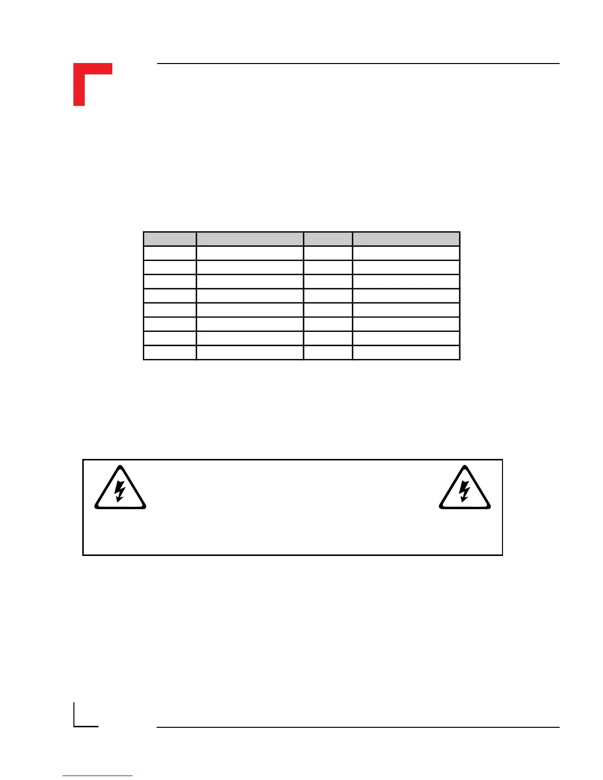
Pin Nr. Signal Pin Nr. Signal
1 Screw Terminal 13 2 Screw Terminal 13
3 Screw Terminal 1 4 Screw Terminal 2
5 Screw Terminal 3 6 Screw Terminal 4
7 Screw Terminal 5 8 Screw Terminal 6
9 Screw Terminal 7 10 Screw Terminal 8
11 Screw Terminal 9 12 Screw Terminal 10
13 Screw Terminal 11 14 Screw Terminal 12
15 Screw Terminal 14 16 Screw Terminal 14
WARNING !
Dangerous voltages may be present at the terminals.