Digital Modules
08 Jan. 98
SMART I/O User’s Manual
Page 4 - 61Manual ID 09901, Rev. Index 0500
Surface-Mounted Devices (SMDs) are used in the production of
SM-ACI1 modules. The components to be changed, marked
with an asterisk in figure 4-5, need not necessarily be SMDs.
Please, refer to the board overview figure (solder side, figure 4-
3) for the approximate position of the jumpers. Notice should be
taken of the fact, that when calculating component values for a
specific filter, the capacitor/resistor relationship is almost linear.
For this purpose, it is suggested that only the capacitor be
changed. Hence, for a doubling of the filter frequency input, the
value of the capacitor should be reduced by half.
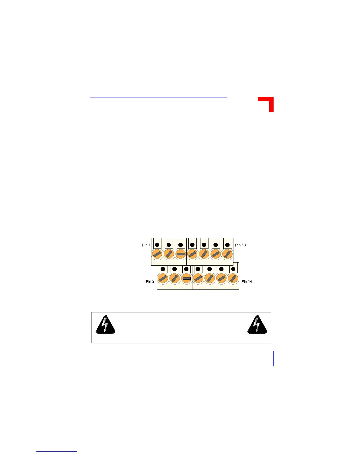
4.4.7Screw Terminal Pinouts
In the following, the pinout/signal relationship for the SM-ACI1,
when connected to a particular screw terminal block, is shown.
Figure 4-6: Screw Terminal Pinout
WARNING!
Dangerous voltages are present at the terminals.