SMART I/O User’s Manual
©1996 PEP Modular Computers GmbHMarch 12, 1996 Page 3 - 9
3
Chapter 3 SMART-EXT
3.4.3 SPI Connectors (ST5 and BU1)
On both sides of the board are standard 2x5 pinrow connectors (BU1, ST5),
that provide the interface connection between SMART-EXT units and the
SMART-BASE.
A 10-wire flat cable is soldered directly on the left-hand side of the board
(BU1), that interfaces the SMART-BASE module or other (earlier cascaded)
SMART-EXT modules.
Pinouts for this 10-pin connector
Note
Pin 10 of BU1 is only useful on the first SMART-EXT connected to the
SMART-BASE. For this reason, SMART-Modules utilizing this feature
can only be connected to the first slot of the first extension unit.
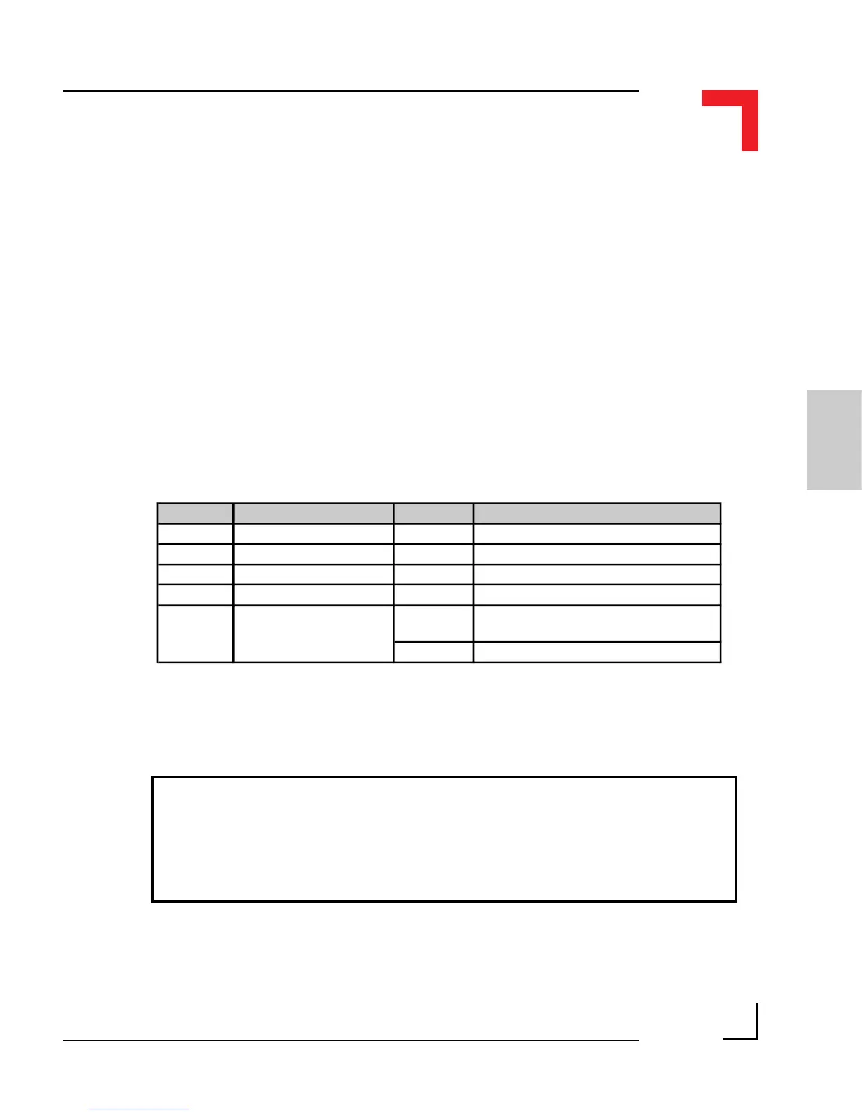
Pin Nr. Signal Pin Nr. Signal
1 System VCC (+5V) 2 Serial RxD from SMART-BASE
3 System VCC (+5V) 4 Serial TxD from SMART-BASE
5 Serial Ext. Select 6 Serial CLK from SMART-BASE
7 System GND 8 Reset (Power ON/OFF)
9 System GND 10 (BU1)
Serial Ext. Interrupt
(INT4 1st Module only)
10 (ST5) N/C