SMART I/O User’s Manual
©1996 PEP Modular Computers GmbHOctober 01, 1996 Page 5 - 109
5
Chapter 5 Analog Modules
5.5.5 Functional Description
The SM-DAC1 has 2, 4 or 6 differential voltage or current outputs depending
on the ordered type. An on-board EEPROM contains board specific calibra-
tion data, module ID byte, sub ID byte and production data. A DC/DC
converter generates the 5V to ±15V power requirements for the D/A con-
verter and provides additional system isolation.
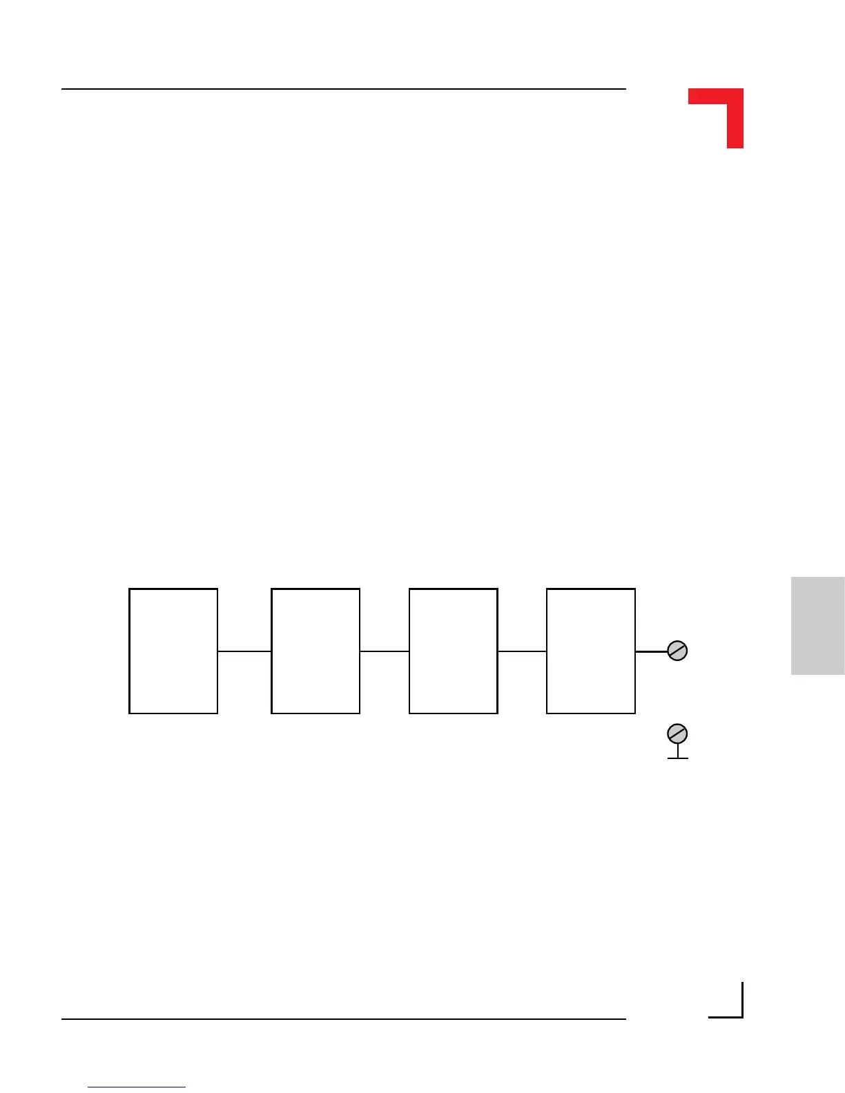
5.5.5.1 Output Circuitry
The output stage of the SM-DAC1 comprises a fast D/A converter followed
by a software controlled switch that ensures the on-board op-amp remains
inactive and produces 0V at it’s output during power-up. The current version
has an additional MOSFET after this op-amp.
Figure 5.5.5.1: SM-DAC1 Output Shematic Diagram
The current version of this module utilizes current sensing that detects open
loads or broken lines. The individual comparators of this sensing circuit
alarm the software when currents below 4mA are detected.
DAC
System
Interface
Operational
Amplifier
AGND
Software
Controlled
Switch
Output