SMART I/O User’s Manual
March 12, 1996
©1996 PEP Modular Computers GmbH
Page 2 - 10
Chapter 2 SMART-BASE
Note
Slot# numbers are counted from #0 up to #10 while the ISaGRAF logic
counts from #1 to #11!
2.5.1 SMART Module Piggyback Connectors
There are three sets of SMART Module piggyback connectors available on
the SMART-BASE, each divided into two sets of 2x8 standard pin rows.
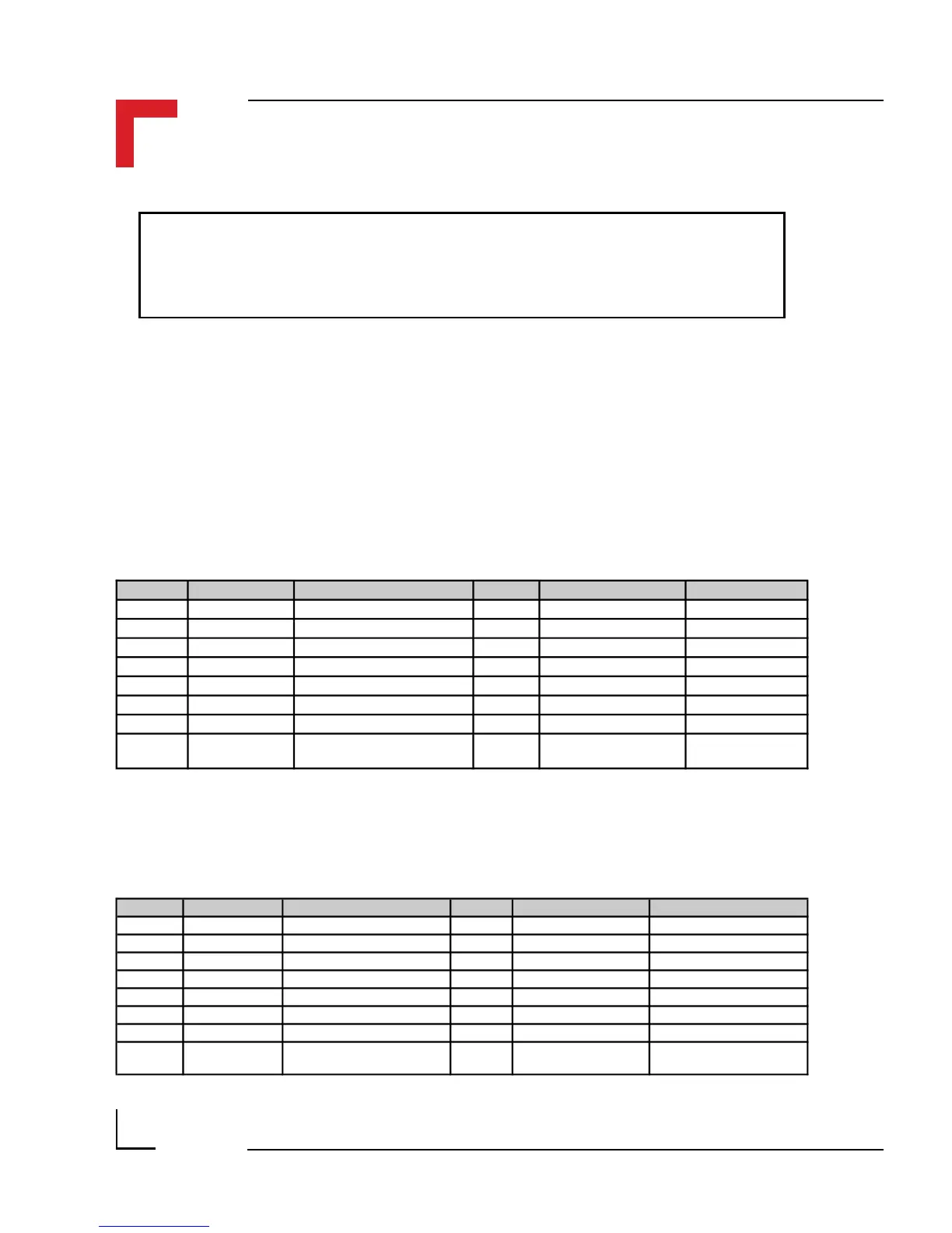
Pinouts digital side (ST1, ST3 and ST5)
SMART-Module location #0 (ST5) pinouts
Pin Nr. Signal Description Pin Nr. Signal Description
1 PITB0 I/O Controller Port B0 2 PITB1 I/O Controller Port B1
3 PITB2 I/O Controller Port B2 4 PITB3 I/O Controller Port B3
5 PITB4 I/O Controller Port B4 6 PITB5 I/O Controller Port B5
7 PITB6 I/O Controller Port B6 8 PITB7 I/O Controller Port B7
9 System GND GND 10 Serial RxD RxD
11 System VCC 5V VCC 12 Serial TxD TxD
13 CS-SM2 Port Select (Module 1) 14 Serial CLK CLK
15 Reset Reset (Power ON/OFF) 16 SM2 Interrupt PI/T
INT2 to the
I/O Controller
Pin Nr. Signal Description Pin Nr. Signal Description
1 PA8 68302 Port A8 2 PA9 68302 Port A9
3 PA10 68302 Port A10 4 PA11 68302 Port A11
5 PA12 68302 Port A12 6 PA13 68302 Port A13
7 PA14 68302 Port A14 8 PA15 68302 Port A15
9 System GND GND 10 Serial RxD RxD
11 System VCC 5V VCC 12 Serial TxD TxD
13 CS-SM1 Port Select (Module 0) 14 Serial CLK CLK
15 Reset Reset (Power ON/OFF) 16 SM1 Interrupt PI/T
INT3 to the
I/O Controller
SMART-Module location #1 (ST3) pinouts