SMART I/O User’s Manual
March 12, 1996
©1996 PEP Modular Computers GmbH
Page 5 - 10
Chapter 5 Analog Modules
5.1.5 Functional Description
The SM-DAD1 has 4 differential voltage inputs and 2 unipolar/bipolar
voltage outputs. An on-board EEPROM contains board specific calibration
data, module ID byte and production data. An on-board switched-mode
regulator provides ±15V for the analog I/O and an additional linear regulator
provides the -5V required by the ADC.
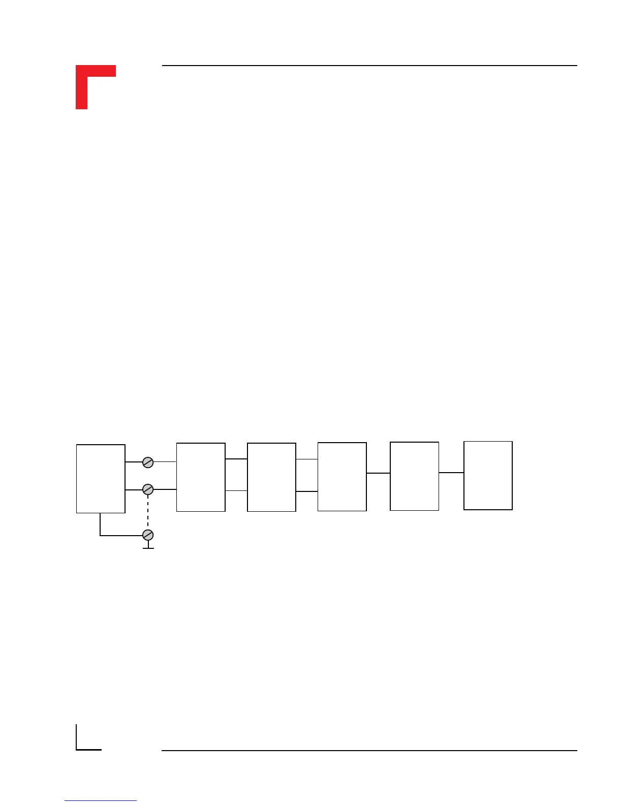
5.1.5.1 Input Circuitry
The input circuitry of the SM-DAD1 consists of an R-C first-order, low-pass
filter to prevent noise and signals greater than 10kHz from entering the
system, a 1:4 channel multiplexer, followed by a differential amplifier,
divider and a 12-bit fast analog to digital converter (ADC).
Figure 5.1.5.1: SM-DAD1 Input Schematic Diagram
The ADC, using successive approximation and input track and hold is
referenced by its own on-chip voltage source supplying 4.096V. To cater for
bipolar full-scale inputs, this reference source is split (-2.048V .. +2.048V).
The incoming voltage signals are multiplexed and reduced via a 1:5 divider
network so that the ADC is supplied with a scalable input voltage range.
Low Pass
Filter
Voltage
Source
-10 .. +10V
Single
Ended
AGND
+
-
MUX
4:1
Input
Amplifier
ADC
System
Interface