SMART I/O User’s Manual
©1996 PEP Modular Computers GmbHMarch 12, 1996 Page 2 - 9
2
Chapter 2 SMART-BASE
2.4.2 Jumper J6: LED Function (Pin Connector)
This jumper selects the function of the red LED; halt or user defined. The
user defined function that is supported in software will only take effect if this
jumper is set accordingly.
Jumper J6 Description
1-3 Processor HALT function monitor
1-2 User defined function
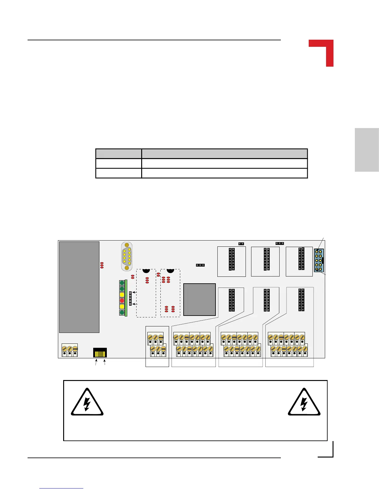
2.5 Pinouts
Figure 2.5.0.1: SMART-BASE Connector Overview
B17
B10
B7
B11
B9
B16 B1
J6
J13
J1
DC/DC
BU2
BU1
SCR2
SCR1
SCR5 SCR4 SCR3
ST6
ST4
ST2
ST5
ST3
ST1
ST7
68302FC20
Pin 1Pin 2
Pin 15Pin 16
Pin 1Pin 2
Pin 15Pin 16
Pin 1Pin 2
Pin 15Pin 16
Pin 1Pin 2
Pin 15Pin 16
Pin 1Pin 2
Pin 15Pin 16
Pin 1Pin 2
Pin 15Pin 16
Pin 1
Pin 2
Pin 10
Pin 9
Pin 1
Pin 2
Pin 13
Pin 14
Pin 1
Pin 2
Pin 13
Pin 14
Pin 1
Pin 2
Pin 13
Pin 14
Pin 1
Pin 2
Pin 5
Pin 6
Pin 1 Pin 2 Pin 3
Pin 1
Pin 5
Pin 6
Pin 9
SMPBLED
BU3
Pin 1
Pin 8
Pin 1
Pin 5
B8
Digital Side
Process SIde
Slot #0 Slot #1 Slot #2
Slot #0 Slot #1 Slot #2
UD LD
EPROM/FLASH
WARNING !
Dangerous voltages may be present at the terminals.