SMART I/O User’s Manual
©1996 PEP Modular Computers GmbHMarch 12, 1996 Page 1 - 15
Introduction
1
WARNING!
Once fitted on the board, the Module sockets and components should be on
the right hand side of the Module.
Screw terminal connectors are available in packs of 5.
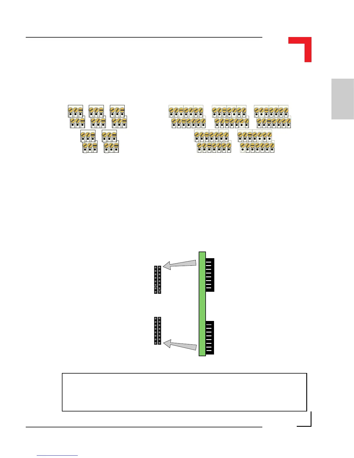
1.4.2 SMART I/O Module Installation
The SMART I/O Modules are fitted into the relevant sockets (ST1 - ST6; 3
slots) on the SMART-BASE or in sockets on the SMART-EXT unit. It is
important that the Modules are inserted the correct way. The Figure
below illustrates this procedure.
Figure 1.4.2.1 : SMART I/O Module Installation
SMART-Module
Socket
SMART-Module