SMART I/O User’s Manual
March 12, 1996
©1996 PEP Modular Computers GmbH
Page 2 - 8
Chapter 2 SMART-BASE
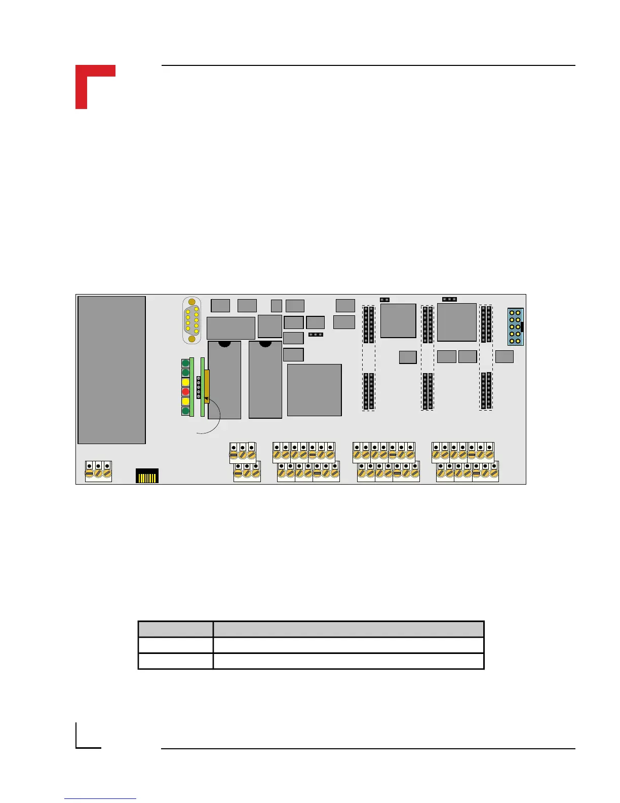
2.4 Configuration
The SMART BASE has 2 configurable jumpers which are explained in the
following sections. The jumper settings marked in italics in the tables are
default.
Figure 2.4.0.1: SMART BASE Jumper Layout (Front View)
J13 J1
DC/DC
BU2
BU1SCR2 SCR1 SCR5 SCR4 SCR3
ST6 ST4 ST2
ST5 ST3 ST1 ST7
DRAM
EPROM/FLASH
(SRAM)
68302FC20
I/O Controller
SPI
I/O Slot #2I/O Slot #1I/O Slot #0
Timer
I/O
RS232
24V DC
RS485 Isolated
(PROFIBUS)
Status
Piggyback
SMPBLED
BU3
Battery
Piggyback
SMPBBAT
SMART Modules
J6
UD LD
EPROM/FLASH
2.4.1 Jumper J1: Boot Selection (Pin Connector)
The jumper J1 selects whether the SMART I/O boots directly from OS-9 or
from ISaGRAF.
Jumper J1 Description
1-3 Application Boot (ISaGRAF)
1-2 OS-9 Shell Boot